
US 29126
UNITED STATES PATENT OFFICE.
A. J. GIBSON, OF WORCESTER, MASSACHUSETTS, ASSIGNOR TO HIMSELF AND I. P. HALE.
IMPROVEMENT IN REVOLVING FIRE-ARMS.
Specification forming part of Letters Patent No. 29,126, dated July 10, 1860.
To all whom it may concern:
Be it known that I, A. J. Gibson, of Worcester, in the county of Worcester and State of Massachusetts, have invented a new and useful Improvement in that class of Fire-Arms known as “Revolvers;” and I do hereby declare that the following is a full, clear, and exact description of the same, reference being had to the accompanying drawings, forming part of this specification, in which—
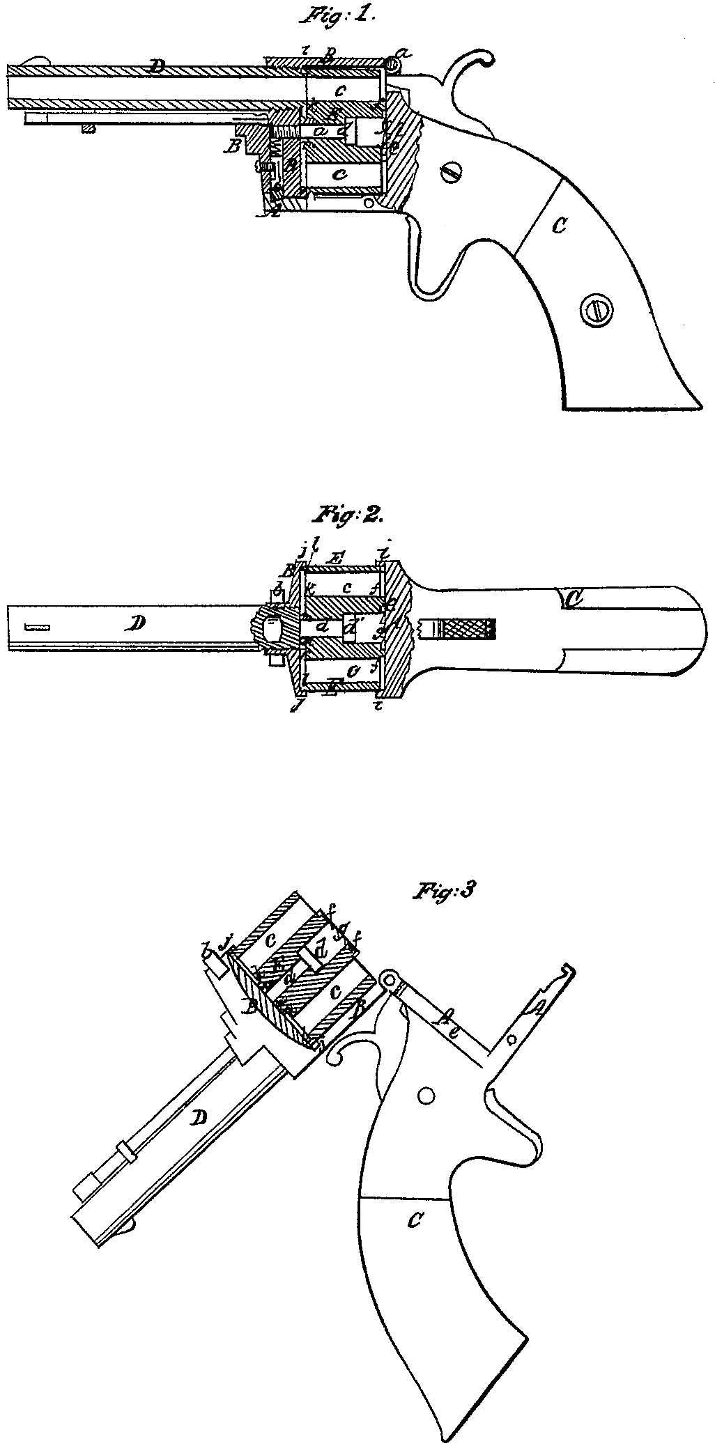
Figure l is a side view, mostly in section, of a pistol constructed according to my invention, representing its parts in proper relative position for use. Fig. 2 is a top view of the same, partly in section. Fig. 3 is a side view, partly in section, representing it in condition for loading.
Similar letters of reference indicate corresponding parts in the several figures.
My invention relates to revolvers of that kind which have a many-chambered cylinder rotating on an axis parallel with a stationary barrel.
The principal object of the invention is to provide greater facility for the loading of the chambers at the rear of the cylinder; and to this end it consists in so applying a chambered cylinder having the chambers extended through the rear, in combination with a frame opening with a hinge joint, that when the frame is opened the cylinder remains attached to and swings with the front part of the frame.
It also consists in the construction of the hinge-jointed cylinder-frame with chambers in its front and rear, to receive within them the entire circumference of the front and rear edges of the cylinder for the prevention of the escape of the fire and the protection of the hand from being burned.
To enable others skilled in the art to make and use my invention, I will proceed to describe its construction and operation.
A and B represent the two pieces of which the cylinder-frame is composed, the piece A constituting the recoil-plate and lower part of the frame, and having the stock C attached, and the piece B constituting the front and upper parts, and having the barrel D secured to it. These two pieces are hinged together at a, above the recoil-plate, and connected by a spring-bolt, b, or other suitable fastening below the barrel.
E is the cylinder, having the chambers c c extended right through its rear. This cylinder is bored out centrally to receive an axis-pin, d, which passes through it and screws into the front part of the piece A of the frame, the said pin having a broad head, d’, which secures the cylinder to the piece, A, and which is countersunk into the rear portion of the cylinder to make the screw entirely independent of the piece B of the frame. By thus attaching the cylinder to the front piece, A, so that when the frame A is opened it (the cylinder) swings away from the recoil-plate e, along with the front part of the frame and the barrel, it is obvious that great facility is afforded for loading at the rear, as on the frame being opened, as shown in Fig. 3, the open rear ends of all the chambers are exposed at once and can be loaded one after the other without moving the cylinder. When the chambers are all loaded the frame is closed up again and the pistol is ready for use.
It is almost unnecessary to say that with the cylinder having its chambers extended right through its rear it will be desirable, if not necessary, to use metallic cartridges, and I propose to use that kind having a flange round the base to contain percussion priming, and for this purpose I provide a space between the cylinder and the recoil-plate all round the cylinder, excepting immediately around the central bore or axis-hole of the cylinder, where I leave a projection, f, to fit against the recoil-plate, and in this projection I form the ratchet notches g g, in which works the dog by which the revolution of the cylinder by the act of cocking the hammer is effected.
The construction of the cylinder-frame with chambers in its front and rear to receive the edges of the cylinder within them is best illustrated in Fig. 2. The chamber in the rear is formed by making a forwardly-projecting rim, i i, all round the recoil-plate, and the chamber in front is formed by making a backwardly projecting rim, j j, all round the front part of the frame, which is made of circular form. The interiors of these rims are made to fit the exterior of the cylinder as snugly as is practicable. The front end of the cylinder has an annular recess, k, formed in it, the mouths of the chambers being in such recess, and the rear muzzle of the barrel projecting into this recess and fitting to the back of it. The surrounding marginal portion l of the cylinder fits up snugly to the front of the frame, and so does the portion m, immediately surrounding the pin d. By thus providing a groove in the cylinder its face is prevented getting clogged with the residuum of the powder.
I do not claim the extension of the chambers through the rear of the cylinder or the construction of the frame in two pieces with a hinge-joint; but
What I claim as my invention, and desire to secure by Letters Patent, is—
1. So applying a so-constructed cylinder, in combination with a so-constructed frame, that when the frame is opened the cylinder remains attached to and swings with the front part of the frame and the barrel, substantially as and for the purpose herein specified.
2. The construction of the hinge jointed cylinder-frame with chambers in its front and rear ends to receive and cover the front edges of the cylinder, substantially as and for the purpose herein specified, also the recess or chamber k in the front or forward end of the cylinder.
A. J. GIBSON.
Witnesses:
Chas. Devins, Jr.,
John Boyden.