
US 29213
UNITED STATES PATENT OFFICE.
CHARLES R, ALSOP, OF MIDIDLETOWN, CONNECTICUT, ASSIGNOR TO JOSEPH W. ALSOP, OF NEW YORK, N.Y.
IMPROVEMENT IN REVOLVING FIRE-ARMS.
Specification forming part of Letters Patent No. 29,213, dated July 17, 1860.
To all whom it may concern:
Be it known that I, Charles R. Alsop, of Middletown, in the county of Middlesex and State of Connecticut, have invented a new and useful Improvement in that class of Fire-Arms known as “Revolvers;” and I do hereby declare that the following is a full, clear, and exact description of the same, reference being had to the accompanying drawings, forming part of this specification, in which—
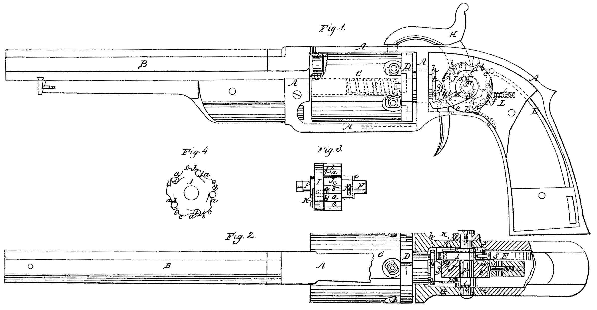
Figure 1 is a side view of a pistol with my improvements, having one of the side plates of the stock removed to show the interior. Fig. 2 is a top view of the same, partly in section. Fig. 3 is a front view of the rotating cam that is employed to force and hold the cylinder forward against the barrel, and of the means of rotating it. Fig. 4 is a view of the opposite side of the cam to that shown in Fig. 1.
Similar letters of reference indicate corresponding parts in the several figures.
My invention relates to those revolvers in which a many-chambered cylinder rotating on an axis parallel with the bore of a stationary barrel is used.
It consists in the employment, for the purpose of moving the cylinder longitudinally toward the barrel before firing and holding it in contact there with while firing, of a cam so applied in rear of the cylinder and combined with the hammer by means of a ratchet and pawl, or their equivalent, that the said cam is caused to make part of a revolution on its axis by the act of cocking the hammer, but is prevented moving back with the hammer in the fall of the latter, such cam being so formed with a regular series of projections and recesses on its perimeter that during the first part of each movement with the hammer it permits the cylinder to move back from the barrel far enough to permit its free revolution, and during the latter part of such movement only is caused to produce the forward movement of the cylinder.
To enable others skilled in the art to make and use my invention, I will proceed to describe its construction and operation.
A is the metal frame, of the usual form.
B is the barrel, and C is the many-chambered cylinder, which may have its axis-pin applied in the mode most commonly adopted or in any convenient manner, and may or may not have applied in connection with it a rotating recoil shield, D.
S (shown in dotted outline in Fig. 1) is a spring, applied to the cylinder in such a manner as to exert a constant tendency to force it back away from the barrel.
F is the hammer-shaft, fitted to a fixed bearing in one side of the back part of the frame A and to a bearing in the movable side plate, G.
His the hammer, secured to the shaft outside the frame, and I is a tumbler secured to the said shaft within the frame. An inside hammer, working through a slot in the top of the frame, as in most other revolvers, may be used, in which case the butt of the hammer will supply the place of the tumbler, the hammer being in any case fast to the shaft.
E is the mainspring, applied to the tumbler in a Well-known manner.
The shaft F is arranged with its axis in the same plane with the axis of the cylinder C.
J is the cam for forcing forward the cylinder, fitted to turn very easily in the hammer-shaft F. The form of the perimeter of this cam is that of a cylinder having a number of similar equidistant concave recesses, a a, and a similar number of ratchet-like notches, b b, which leave a similar number of equidistant and similar concentric arc-formed faces or projection, c c. In the example represented there are five of such projections, notches and recesses; but a larger number may be used, six being, I believe, the number that can be used with greatest advantage. On one side of the said cam, which fits close up against the tumbler, there is a number of equidistant notches, d d, corresponding with the number of notches, projections, and recesses in its periphery, such notches d d being of a ratchet-like character, and having their square or abrupt sides facing in the same direction as the square or abrupt sides of the notches b b— that is to say, in the same direction in which the hammer moves in falling.
K is a spring-pawl attached to the opposite side of the tumbler to that on which the cam J is arranged, and having its tooth e working through a hole in the tumbler, said tooth being in range with the notches d d. The movement of the hammer from full-cock to the position in which it effects the firing is just sufficient to move this tooth e from one notch d to the next one. As the hammer is drawn back to cock it the tooth e of the pawl K engages in one of the notches d d and causes the cam to move with the hammer, and so to make a sufficient portion of a revolution in the direction of the arrow shown upon it in Fig. 1 to move away one of its projections c c from a position opposite to the cylinder and to bring another of such projections to a similar position; but as the hammer moves forward or falls the cam is prevented moving with it by the action of a spring-stop, f, in one of its notches b b, said stop being applied within the solid recoil-block L, that is provided in the frame A in rear of the cam to constitute a bearing for it in its action on the cylinder and to sustain it against the recoil of the cylinder, and being so arranged as to stop the cam with one of its projections c c opposite to the cylinder. In the forward movement or fall of the hammer the tooth e of the pawl K passes over the beveled side of one notch d and drops into the next one. The rounded face g at the end of the rear journal of the cylinder or rotating recoil-shield, or of a regulating-screw screwed thereinto, is always kept in contact with the cam J by the spring S. In each cocking movement of the hammer, as soon as the projection c which has previously been opposite to the cylinder passes the face g the spring S forces the cylinder back out of contact with the barrel, and holds it back while the next notch b and recess a are passing the said face g, and so permits the revolution of the cylinder during that time; but as the next projection c of the cam arrives opposite the face g the cylinder is again forced forward by the action of the rising side of the recess a, and when the hammer arrives at full-cock the center of the face of a projection c is always opposite the center of the cylinder, and the cylinder is held up to the barrel not only while the hammer remains cocked, but while the firing is effected, for, as has been before stated, the cam does not move back with the hammer, but is only permitted to move in the direction of the arrow shown upon it in Fig. 1.
The rotation of the cylinder is effected by means of an arm, M, fitted to the shaft F, and operating on a series of ratchet-teeth, h h, on the cylinder itself or on the recoil-shield, the said arm being fitted loosely to the shaft, but being secured thereto by a pin, i, which is inserted tightly in a hole in the said shaft, and which enters a notch, g, in the hub of the said arm, the said notch being wide enough to permit the shaft and the cam J in the cocking operation to move far enough to let the cylinder move back out of contact with the barrel before the arm M comes into operation to produce the rotary movement of the cylinder.
Instead of the cam J being applied directly to the shaft of the hammer, it may be applied in the same manner to the shaft or axis-pin of a cocking lever or trigger in a revolver which is cocked by such means, in which application it will be operated by a pawl like K, attached to the cocking-lever, and its operation will be the same in this indirect combination with the hammer as in the direct combination herein before described, and represented in the drawings.
What I claim as my invention, and desire to secure by Letters Patent, is—
1. The employment, for the purpose of forcing forward the cylinder longitudinally toward the barrel before firing and of permitting its movement longitudinally away from the barrel, of a cam formed with a regular series of projections and recesses on its periphery, applied substantially as herein described, and rotating in one direction only.
2. Combining such cam with the hammer, either directly or indirectly, by a ratchet and pawl or their equivalent, in such manner as to be operated by the cocking of the hammer, substantially as herein described, but to remain stationary during the fall of the hammer.
CHAS. R. ALSOP.
Witnesses:
Clark Elliott,
Jonathan Barnes.