
US 29538
UNITED STATES PATENT OFFICE.
CHAS. R. ALSOP, OF MIDDLETOWN, CONNECTICUT, ASSIGNOR TO J. W. ALSOP, OF NEW YORK, N.Y.
IMPROVEMENT IN RAMMERS FOR REVOLVING FIRE-ARMS.
Specification forming part of Letters Patent No. 29,538, dated August 7, 1860,
To all whom it may concern:
Be it known that I, Charles R Alsop, of upper edge of Middletown, in the county of Mildlesex and State of Connecticut, have invented a new and useful Improvement in Rammers for Revolver Fire-Arms; and I do hereby declare that the following is a full, clear, and exact description of the same, reference being had to the accompanying drawings, forming part of this specification, in which—
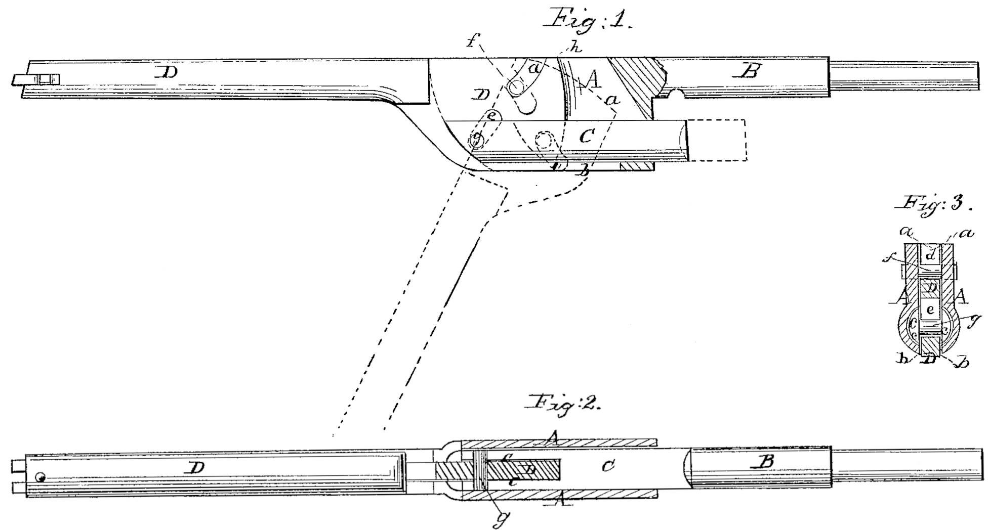
Figure 1 is a side view of a rammer, partly in section. Fig. 2 is a horizontal section of the same. Fig. 3 is a transverse section of the same.
Similar letters of reference indicate corresponding parts in the several figures.
This invention consists in combining the plunger of the rammer with its operating-lever and with a rammer-frame that is detachable from the stock by means of a fixed fulcrum-pin in the frame, a transverse pin secured in the rammer, and two slots arranged in the lever, as hereinafter described, such mode of combining the plunger-lever and frame providing for the operation of the lever with gradually-increasing effect in ramming the charges into the chambers and providing for the easy disconnection of the lever and plunger from the frame when the frame is detached from the body of the arm.
To enable others skilled in the art to make and use my invention, I will proceed to describe its construction and operation.
A is the rammer-frame, which may constitute the head of the cylinder axis-pin B, or be otherwise made separate and detachable from the body of the arm. The said frame is bored out cylindrically and longitudinally to receive the plunger C, and has a slot, a, above and a slot, b, of the same width below the said cylindrical bore, the said slots being exactly opposite each other, as shown in the transverse section, Fig. 3. The plunger C has in its front part a slot c, of the same width as a and b. These slots a b c receive the lever D, the head of which is made of a depth equal to the whole depth of the frame A, and of such width or thickness as to work easily within the slots a b c.
d and e are the slots in the head of the lever. The slot d is of curved form, commencing in the upper edge of the head, near the edge thereof, and has a forward inclination toward its bottom, extending to a little more than half the depth of the slot a, its concave side being toward the rear of the lever. The slot e, which is lower down and in front of the slot d, is straight, and is at an angle of about fifty-five degrees to the length of the lever, its lower end being nearest the front or handle of the lever.
f is the fulcrum-pin, crossing the slot a of the head A, in the sides of which it is secured, and passing through the slot e of the lever.
g is a pin, fitted snugly to holes in the sides of the slot c of the plunger, crossing the said slot and passing through the slot e of the lever, and serving to attach the plunger to the lever.
The operation of the rammer is as follows: When the front end of the lever is drawn down from the position in line with or parallel with the cylinder axis-pin represented in black out line in Fig. 1 the upper corner, h, of the rear end of the lever comes in contact with the barrel, and its curved slot d slides down the fulcrum-pin f, and the lever, swinging on this pin, brings its slot e into action on the ping of the rammer. As the lever moves down, the distance between f and g diminishes, and its leverage on the plunger increases, while its action is aided by the cam-like action of the curved slot on the fulcrum-pin. In moving up the lever to draw back the plunger the action is reversed. When the frame A is detached from the arm the lever and plunger can be easily drawn out from the frame by pulling it endwise, and at the same time raising its front end, the slot d in such operation slipping off the pin f.
What I claim as my invention, and desire to secure by Letters Patent, is—
Combining the plunger C with the lever D and the frame A by means of the two pins f g and the two slots d e, substantially as herein specified.
CHAS. R. ALSOP.
Witnesses:
Clark Elliott,
Jonathan Barnes.