
US 29864
UNITED STATES PATENT OFFICE.
J. MASLIN COOPER, OF PITTSBURG, PENNSYLVANIA.
IMPROVEMENT IN REVOLVING FIRE-ARMS.
Specification forming part of Letters Patent No. 29,864, dated September 4, 1860.
To all whom it may concern:
Be it known that I, James Maslin Cooper, of the city of Pittsburg, in the county of Allegheny and State of Pennsylvania, have invented certain new and useful Improvements in Revolving Breech Fire-Arms; and I do hereby declare the following to be a full, clear, and exact description thereof, reference being had to the annexed drawings, forming part of this specification, in which—
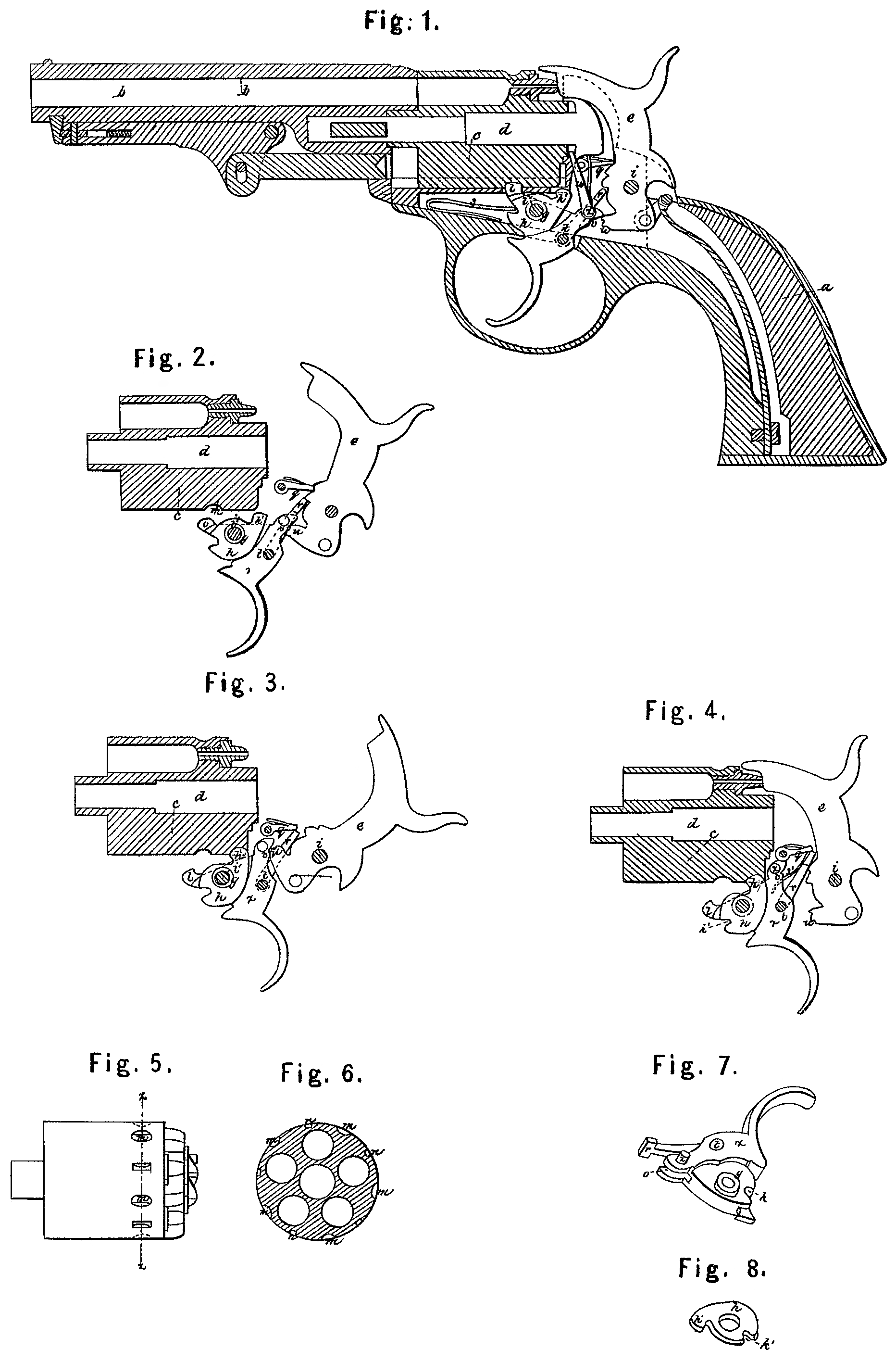
Figure 1 is a longitudinal section of a revolving fire-arm constructed with my improvements, and showing the several parts of the lock at rest before firing. Fig. 2 represents the revolving breech in section and aside view, of the hammer and trigger and other parts of the lock, excepting the driver for revolving the breech, in their position when the hammer is raised to half-cock either by raising the hammer or pulling: the trigger. Fig. 3 is a similar view of the. revolving breech and hammer, trigger, and other parts of the lock, except the driver, when the hammer has been raised to full-cock by means of the trigger and is standing in that position. Fig. 4 is a view of the revolving breech and other parts of the lock when the hammer has fallen to. fire the piece and before the trigger has been allowed to react. Figs. 2 to 4, inclusive, are designed to show the relative position and bearing of the parts. represented, and the lock-frame, spindle, and main and trigger springs are not shown. Fig. 5 is a side view of the revolving breech, showing the recess in its circumference to receive the locking-bolt. Fig. 6 is a section of the revolving breech through 2 x, Fig. 5, at right angles to its axis. Fig. Tis a perspective representation of the trigger of my pistol, showing the projection for locking the cylinder so as to be safe from accidental discharge, the collar around the trigger-pin, on which the locking-bolt turns. Fig. 8 is a perspective representation of the locking-bolt detached from the trigger. In. Fig. 7 the trigger is turned upside down, and in Fig. 8 the locking-bolt is in a corresponding position.
In the several figures like letters of reference denote similar parts.
My improvements consist in the peculiar arrangement and construction of the parts of the lock, whereby I secure greater ease in firing and reduce the sween of the trigger; also, in the use of a projection at the end of the trigger, in combination with recesses in the circumference of the rotating breech, whereby, when the trigger is not drawn back, the revolving breech may be secured in such a position that the end of the hammer will rest against the breech between two of the nipples and not upon one of them, thus avoiding in a great measure the danger of premature or accidental discharge of the piece; also, in the use of a locking-bolt for fastening the breech at the moment of firing, operated by the trigger and trigger-spring, and working on a collar around the trigger-pin, so as to secure it from any pressure of the lock-frame, thus securing certainty of action and simplicity of construction.
One of the peculiarities of the arrangement of the parts of the lock of my pistol is that by keeping. the toe of the hammer always underneath the point of the trigger, so that the trigger need not pass it when reacting after firing, I save a portion of the sweep of the trigger, the length of which has been an objection to trigger-operating fire-arms. This I. obviate in a great measure by the hammer, trigger, and vibrating tooth, as hereinafter described.
In the drawings, a represents the stock of the pistol; b, the barrel; c, the revolving cylinder or breech, which rotates on its axis on the spindled. These parts, with the exception of the notches on the breech, may be of ordinary construction. The hammer e is fastened to the lock-frame by a hammer-pin at i. The trigger f is pivoted to the lock-frame at it. The front end of the trigger, around the hole through which the trigger-pin passes, is reduced in thickness on one side only, excepting close around the hole for the trigger-pin where it is left the full thickness, making a collar around. the trigger-pin hole, as seen at g, Fig. 7. On this collar g is placed the locking-bolt h, (see Fig. 8,) which is made of a plate of steel, some what thinner than the recess formed by reducing the thickness of the trigger at that point. Thus the collar g sustains the pressure of the sides of the lock-frame and prevents any interference with the free action of the locking: bolt, which is very important to the perfection. of revolving fire-arms. This locking-bolt has a head at h’, which passes through a slot in the lock-frame and engages the front end of the rotating breech in notches between the nipple, so as to lock it in the exact position requisite for firing. The head of the locking-bolt is pressed up, in the act of firing, by the mechanical pressure of the trigger when drawn back. The trigger-springs enters a recess, k, in the trigger, and a corresponding recess, k”, in the locking-bolt, which, while it keeps the trigger forward when the parts of the lock are at rest, also keeps the head of the locking-bolt disengaged from the breech, except just previously to the time of firing.
There is a projection, l, on the front end of the trigger, which passes through a slot in the lock-frame and engages the recesses n n, &c,. in the circumference of the rotating breech, which are so situated that when the projection l enters, a recess, n, in the breech the breech shall be secured from rotation until the trigger is again pulled, and shall be so situate in relation to the hammer that the hammer shall not rest upon nor be in range with any of the nipples, but between two of them, and thus the possibility of discharge of the piece by the hammer striking any of the nipples is obviated.
Intermediate between the recesses n n in the face of the breech are depressions on, with sloping sides, so as to allow the trigger to come forward after the pistol is fired, and yet permit the breech to be turned until the projection on the trigger enters one of the safety-recesses n, the sides of which being straight, the breech cannot turn until the trigger is drawn. This difference between the depressions m and safety-recesses n is shown in Fig. 6.
On the trigger is a vibrating tooth, r, (see Fig. 7,) which is pivoted to the trigger at t, so as to work in a recess, o, in the front end of the trigger. It is pressed up against the face of the hammer by a small spring, s’. (See in Fig.4.) This vibrating tooth is so arranged in connection with the hammer as that as point rests in a notch in the face of the hammer at f when the hammer is down, and on drawing the trigger the vibrating tooth, pressing upward against the face of the hammer, raises it first to the point of half-cock, (shown in Fig. 2,) at which it is retained by the pawl 1, as seen in Fig. 2. On further drawing back the trigger the hammer is still further raised until the point of the vibrating tooth r passes out of the notch and carries the pawl q out of the descent of the hammer, as seen in Fig. 3, so that it falls clear upon the nipple of the revolving breech and fires the piece. When the pistol is at half cock, as in Fig. 2, it will be noticed that the revolving breech is not locked, either by the head of the locking-bolt h or by the projection l at the end of the trigger, and thus the breech is free to be rotated by hand for loading, or otherwise, whenever the hammer is raised to half-cock, either by drawing the trigger or raising the hammer by hand.
When it is desired to cock the pistol before firing it is done by raising the hammer by hand, in which case the toe of the hammer presses against the point of the trigger, raising it up and drawing back the trigger until the parts assume the position shown in Fig. 3, of full-cock, in which position the parts are retained by a hook or point, u, at the toe of the hammer, which rests upon a ledge or neck, v, on the under side of the toe of the trigger. The shape of the toe of the hammer and point of the trigger is seen better in Fig. 1.
It will be seen by examining Figs. 1 to 4. which show the various relative positions of the hammer, trigger, and locking-bolt before. and during the act of firing and after firing, that the point of the trigger never passes under the toe of the hammer, but rests against it, the action of the hammer om the trigger during the raising of the hammer by hand. being very slight, the point of the hammer slipping along the toe of the trigger until the hook on the hammer engages the ledge on the trigger and never passing over it, so that the pistol cocks with but little sweep of the trigger. When the pistol is cocked by hammer the vibrating tooth serves to keep the pawl g out of the road on the descent of the hammer, and is also necessary to render the pistol-trigger operating as well.
The driver for revolving the rotating breech the proper degree to bring a bore in the breech in line with the barrel is seen at w, Fig.1, near the point of the trigger, being placed on the pin x. (See Fig. 7.)
Having thus described my improvement in revolving fire-arms, what I claim as my invention, and desire to secure by Letters Patent, is—
1. The use of a locking-bolt such as described, operated by the trigger-spring and trigger, working on a collar on the trigger, around the trigger-pin, so as to prevent its action being interfered with by the pressure of. the sides of the lock-frame.
2. The use of a projection at the front end of the trigger, projecting through the lock frame and pressing against the circumference. of the rotating breech, in combination with suitable recesses in the circumference of the rotating cylinder, whereby, when the trigger is not drawn back and the parts are at rest, the cylinder will be secured from rotation in such a position that the end of the hammer will be situate between two of the nipples and not upon or in front of any of them, thus avoiding in a great measure the danger of a premature or accidental discharge.
3. The arrangement of the trigger hammer, and vibrating tooth, constructed as described, for the purposes hereinbefore described.
J. MASIN COOPER.
Witnesses:
Benjn. F. Sheldon,
Martin G. Cushing.