
US 30260
UNITED STATES PATENT OFFICE.
AUGUST SPELLIER, OF PHILADELPHIA, PENNSYLVANIA.
IMPROVEMENT IN REVOLVING FIRE-ARMS.
Specification forming part of Letters Patent No. 30.260, dated October 2, 1860.
To all whom it may concern:
Be it known that I, August Spellier, of the city of Philadelphia and State of Pennsylvania, have invented certain new and useful Improvements in Revolving Fire-Arms; and I do hereby declare the following to be a full, clear, and exact description of the same, reference being had to the accompanying drawings, and to the letters of reference marked thereon.
My invention consists in a spring or its equivalent connected to and arranged on the frame which carries the revolving breech in respect to the latter and to the hammer in the manner described hereinafter, so that the fire-arm may be used for metallic cartridges or ordinary charges, as fully described hereinafter.
In order to enable others to make and use my invention, I will now proceed to describe its construction and operation.
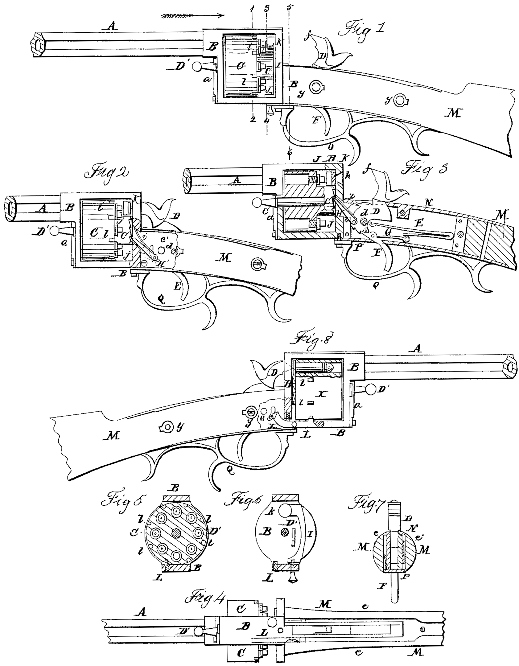
On reference to the accompanying drawings, which form a part of this specification, Figure 1 is an exterior side view of my improved revolving fire-arm as arranged for the use of ordinary charges; Fig. 2, the same as Fig.1, but partly in section; Fig. 3, a sectional view of Fig. 1; Fig. 4, an inverted plan view of Fig. 1, with the under plate of the lock removed; Fig. 5, a transverse section of Fig. 1 on the line 12; Fig. 6, the same on the line 3 4; Fig. 7, the same on the line 56; and Fig. 8, a side view, partially in section, with a revolving breech arranged to receive metallic cartridges.
Similar letters refer to similar parts through out the several views.
A is the barrel of my improved revolving fire-arm, and B is the frame, within which is hung the revolving breech C on a breech-pin, D’, the latter passing through the frame, and being retained in its position by a spring, a, a projection on which bears against a collar on the said breech-pin, as best observed on reference to Fig. 3.
Two plates, e and e?, Figs. 4 and 7, are secured to or form a part of the frame B, there being space sufficient between the two plates to admit the hammer D, the mainspring E, the end of the trigger F, and its spring G. The hammer, which fits snugly but so as to move freely between the two plates e and e’, is hung to a pin, d, and has a partially-rounded edge, f, formed to strike against the rear of the metallic cartridges, as seen in Fig. 8, the said edge, when the hammer is down, passing through an opening, h, in the rear of the frame B. The lower edge of the hammer is provided with two notches for receiving the point of the trigger, as in ordinary fire-arms, so that the hammer may be set at full or half cock at pleasure. The springs E and G are arranged as usual, the former to act on the hammer and the latter on the trigger.
To a pin on the hammer D is hung a dog, H, situated on the outside of the plate e, the pin passing through a curved slot in the said plate, as best observed on reference to Fig. 2, a spring, i, bearing against the frame and attached to the dog, serving to depress the point of the latter when it is not raised by the cocking of the hammer. This dog H is arranged to catch into the ratchet-teeth at the rear of the projecting portion c of the revolving breech, which in this instance is provided with eight chambers for receiving as many charges, and consequently with eight ratchet-teeth and eight nipples, j, one to each chamber, as in ordinary revolving fire-arms.
On the inside of the rear end of the frame B is a spring, I, so secured by a clamp-screw to the lower end of the frame as to be readily detached therefrom, the spring being provided at the top with a circular hub or projection, k, so arranged as to coincide with the nipple of that chamber which coincides with the barrel, the rear of the projection being in a position to be struck by the point f of the hammer when the latter descends.
It should be understood that the spring I is so arranged that its projection shall be free from contact with the caps on the nipples at all other times excepting when the hammer descends and strikes the rear of the spring.
It will be observed that on the collar of the revolving breech, to which the nipples are secured, there are as many notches l l as there are chambers.
A projection on the lever L (see Fig. 8) is arranged to fit into these notches as the breech revolves, the said lever I being situated in a slot in the frame B and being hung to a pin connected to the said frame.
A spiral spring in a recess in the rear of the frame and pressing on the edge of the lever serves to retain the projection of the latter in one of the notches of the breech.
A pin, x, attached to the hammer, passes through a curved slot in one of the side plates, e, and, projecting beyond the latter, so acts upon the bent end of the lever L that when the hammer is raised the pin x raises the bent end of the lever and removes its projection from the notch in the breech c, as more fully explained hereinafter.
M is a portion of the stock of the fire-arm, which is secured to the frame B and its two plates, e and e’, in the following manner: A simple slot (see Fig. 7) is cut into the end of the stock, the slot being wide enough to admit the two plates e and e’, with their adjuncts, and long enough to allow the forked end of the stock to bear against the rear of the frame B. The stock is secured to the plates e and e’ by the screws y y, and an upper plate, N, with an opening large enough to allow the hammer to play freely, is secured at one end to the stock and at the opposite end to the side plates, to which is also secured a plate, z, in front of the hammer. A trigger-plate, P, and guard Q are also secured at one end to the stock and at the opposite end to the frame B.
In the use of fire-arms metallic cartridges are preferred on account of the rapidity with which they can be inserted in their proper position in the breech compared with the time occupied in charging the chambers with powder and ball in the usual manner. There is much difficulty, however, in procuring supplies of metallic cartridges at all times, especially in distant localities, and as fire-arms are prepared to receive cartridges of this class only become useless when the supply is exhausted, those prepared for ordinary charges, although much time is lost in loading, will be preferred.
The main object of my improvements has been to produce a fire-arm in which metallic cartridges can be used, and which, when the supply of these cartridges is exhausted, may be arranged to receive the ordinary charges. For this purpose it becomes necessary to use two different revolving breeches— one for the ordinary charges, as seen in Figs. 1, 2, and 3, and one for the metallic cartridges, as seen in Fig. 8, the hammer, as before described, being arranged to strike the metallic cartridge with its sharp edge. When the fire-arm has to be used for ordinary charges, however, the breech-pin D’ is withdrawn after simply moving back the spring a, when the revolving breech X, Fig. 8, is removed from the frame B and replaced by the revolving breech C. As the point of the hammer, however, is not adapted to strike the caps on the nipples j, I use the spring I, which has been previously described. As the hammer descends it strikes the back of the spring, the projection k of which strikes the cap on the nipple, and an explosion ensues with as much certainty as though the cap had been struck by a hammer of the ordinary construction. It will be evident, therefore, that by the use of this simple spring I and two different revolving breeches the fire-arm may be readily adapted for the use of either metallic cartridges or the ordinary charges.
Another part of my improvement consists in the device for retaining the breech in its proper position, so that each chamber in succession may coincide exactly with the bore of the barrel. When the hammer has descended, as seen in Fig. 8, the projection on the lever L fits into one of the notches of the breech, thereby maintaining the latter in its proper position. When the hammer is raised, however, the pin x acts on the lever so as to withdraw its projection from the notch, immediately after which the continued movement of the hammer causes the dog H to act on one of the ratchet-teeth at the back of the revolving breech, causing the latter to turn to the extent of one-eighth of its circumference, so that the chamber, next to that which had last been discharged will coincide with the barrel. Prior to the breech reaching its destination, however, and before the hammer had arrived at the position of full-cock, the pin x had left the bent end of the lever L, the projection on which (the lever being urged by the spiral spring previously alluded to) will be ready to drop into the next notch when the revolving breech has completed its movement and the hammer has arrived at the position of full-cock. When the hammer descends the pin x will not interfere with the lever L, for the end of the latter and the pin are so constructed that as the pin descends the lever will move out laterally, and be thus freed from the blow which the sudden movement of the pin would otherwise impart.
It will be evident without further description that by the above device each chamber in succession is retained in its proper position to coincide with the barrel.
I do not desire to claim broadly, the employment of a lever operated by the trigger for the purpose of retaining the revolving breech in a proper position; but
I claim as my invention and desire to secure by Letters Patent—
The spring I, or its equivalent, connected to and arranged on the frame B in respect to the revolving breech and hammer D substantially as specified.
In testimony whereof I have signed my name to this specification in the presence of two subscribing witnesses.
AUGUST SPELLIER.
Witnesses:
Henry Howson,
Charles D. Freeman.