
US 30245
UNITED STATES PATENT OFFICE.
E. A. PRESCOTT, OF WORCESTER, MASSACHUSETTS.
IMPROVEMENT IN REVOLVING FIRE-ARMS.
Specification forming part of Letters Patent No. 30,215, dated October 2, 1860.
To all whom it may concern:
Be it known that I, E. A. Prescott, of Worcester, in the county of Worcester and State of Massachusetts, have invented a new and useful Improvement in Revolver Fire-Arms; and I do hereby declare that the following is a full, clear, and exact description of the same, reference being had to the annexed drawings, forming part of this specification, in which—
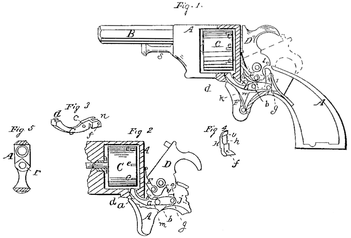
Figure 1 is a side view, partly in section, of a revolver with my improvement. Fig. 2 is a side view of the interior of the lock, showing the parts in a different position to Fig. 1. Fig. 3 is a perspective view of the dog which locks the cylinder. Fig. 4 is a perspective view of the small elbow-lever by which the unlocking of the cylinder is effected, showing the inner side, which is turned a way from the eye in Figs. 1 and 2. Fig. 5 is a transverse section of the frame in front of the cylinder.
Similar letters of reference indicate corresponding parts in the several figures.
My invention consists in a novel, simple, and effective mechanism for locking and unlocking the cylinder, whereby it is caused to be positively locked while the hammer is cocked, and while it is down and during its whole striking movement, and only unlocked at that stage of the cocking operation during which the rotary movement is required to be effected.
It also consists in furnishing the front part of the frame with a projection extending in a rearward direction and surrounding the cylinder axis-pin in front of the cylinder, and having the part above the said pin made V-shaped and sharp-edged for the purpose of scraping off from the front of the cylinder any dirt that may result from the firing of the charges, and preventing such dirt finding its way between the cylinder and pin and clogging the operation of the cylinder.
To enable others skilled in the art to make and use my invention, I will proceed to describe its construction and operation.
A is the frame; B, the fixed barrel; C, the rotary many-chambered cylinder, all constructed and combined substantially in the usual manner.
D is the hammer, and E the attached dog for effecting the rotation of the cylinder, both constructed and applied and operating as in other well-known revolvers.
F is the trigger, having the sear a attached, fitted to a slot in the bottom of the frame A, and working in the usual manner on a pin, b, which is inserted through the frame across the slot in Which the trigger is received. On one side of this trigger there is formed a cavity, m, for the reception of the locking-dog G, which works in the same slot. This dog, which is of the lever-like form best shown in the perspective view, Fig. 3, has a hole, c, drilled through it, to fit the trigger-pin b, which constitutes its fulcrum, and it has a tooth, d, on the top of its front extremity, to fit a series of abrupt notches, e e, in the rear portion of the outer periphery of the cylinder, and has a mortise, n, in its rear end for the reception of the small elbow-shaped unlocking-lever H, which is attached to it by means of a pin, g, passing through holes f f in the said lever and dog. This lever H has in the side nearest the hammer a recess, h, whose upper edge inclines downward and rearward in the manner shown at i in Fig. 4, and the said lever has its upper extremity curved downward and rearward.
j is a small spring attached to the inside of the frame, to press gently against the back of the upper part of the unlocking-lever. k is a spring secured within the trigger-slot of the frame and pressing upward against the front part of the locking-dog G. This spring k must exert so much force, compared with the spring j, that it will hold up the front part of the dog G despite the tendency of the action of the spring jupon the lever H to raise the rear end of the said dog. l is a pin-stud projecting from the side of the hammer next the unlocking-lever H. This stud, which is of such length that it will pass through the recess h of the unlocking-lever, is rounded at its bottom and rear and angular at its top and front, as shown in Figs. 1 and 2. When the hammer is down or against the nipple, as shown in black outline in Fig. 1, the stud l occupies a position above and out of contact with the top of the unlocking-lever H, and the tooth d of the dog is held in one of the notches e e of the cylinder by the upward pressure of the spring k upon the dog, while the lower arm of the lever EI is held in contact with the frame behind the trigger-slot by the forward pressure of the spring j on its upper arm; but in drawing the hammer back by hand to cock it the stud l is brought into contact with the curved upper end of the lever H, and in passing over it is caused to drive it forward and to press the extremity of the lower arm against the frame in such a manner as to raise the pin g and the rear end of the locking-dog, and so to depress the front end of the said dog and remove its tooth d from the notch in the cylinder, as shown in Fig. 2, at the proper time to permit it to be rotated by the dog E; but as, in the continued backward movement of the hammer after the rotation of the cylinder has been effected, the stud l passes over to the rear of the lever to a point below the upper edge, i, of the recess h, the dog G is liberated, and its spring k overcomes the pressure of the spring j and throws the dog into the next notch, e, which has been brought opposite to it by the rotation of the chamber, and so locks the cylinder again and throws back the upper end of the lever H. The hammer is shown cocked in Fig. 1 in red outline. In the striking movement of the hammer the dog G remains undisturbed, for the stud l in this movement, passing through the notch h of the unlocking-lever and by its action on the inclined upper edge, i, pushes back the lever H out of its way. Before or by the time the hammer has struck the spring i has thrown forward the upper end of the lever EI again under the stud l, as shown in black in Fig. 1. Thus it will be understood the same tooth, d, keeps the cylinder always locked, except during the time occupied in its rotation.
r, Figs. 1, 2, and 5, is the rearward projection from the front of the frame surrounding the cylinder axis-pin s. Fig. 5 shows the V shape of its upper part, and Figs. 1 and 2 the manner in which it is beveled to scrape the front of the cylinder in whichsoever direction the latter rotates. This projection r is formed upon a small thimble, which is driven tightly into a suitable hole in the frame, as shown in Fig. 2.
What I claim as my invention, and desire to Secure by Letters Patent, is—
1. The combination of the lever-like locking dog G, the elbow-shaped unlocking-lever H, and the stud l, the whole applied and operating in connection with and relatively to the hammer, substantially as herein specified.
2. The rearward projection on the front part of the frame, having its upper part made V shaped and sharp-edged, as illustrated in Figs. 5 and 2, for the purpose herein specified.
E. A. PRESCOTT.
Witnesses:
Appleton Cushman,
Jason Chapin.