
US 527166
UNITED STATES PATENT OFFICE.
ARTHUR J. WATSON, OF MEAN MEER, INDIA.
RELOADING CARTRIDGE-HOLDER.
SPECIFICATION forming part of Letters Patent No. 527,166, dated October 9, 1894.
Application filed July 3, 1894. Serial No. 516,518. (No model.)
To all whom it may concern:
Be it known that I, ARTHUR JOHN WATSON, major Suffolk Regiment, a subject of the Queen of Great Britain and Ireland, lately of the Junior United Service Club, Charles Street, in the county of Middlesex, England, but now at Mean Meer, Punjab, in the Empire of India, have invented certain Improvements in Apparatus or Devices to Enable All the Chambers of Revolvers or Like Firearms to be Simultaneously Loaded with Cartridges, of which the following is a specification. The object of this invention is to provide simple and efficient apparatus or devices by means of which all the chambers of revolvers or like firearms can be simultaneously loaded with cartridges.
The apparatus or device constructed according to this invention consists of a cylinder or holder (which for the sake of lightness may be made of aluminium) containing chambers in number and relative position corresponding to the number of chambers in the revolver and of a diameter slightly larger than that of the base rim of the cartridges with which the revolver is to be loaded. A cover is fitted to the cylinder or holder so that it can be rotated to lock the cartridges in the cylinder or holder, or release the same therefrom in loading a revolver or other fire-arm.
In order that my said invention may be fully understood I shall now proceed more particularly to describe the same and for that purpose shall refer to the several figures on the annexed sheet of drawings the same letters of reference indicating corresponding parts in all the figures.
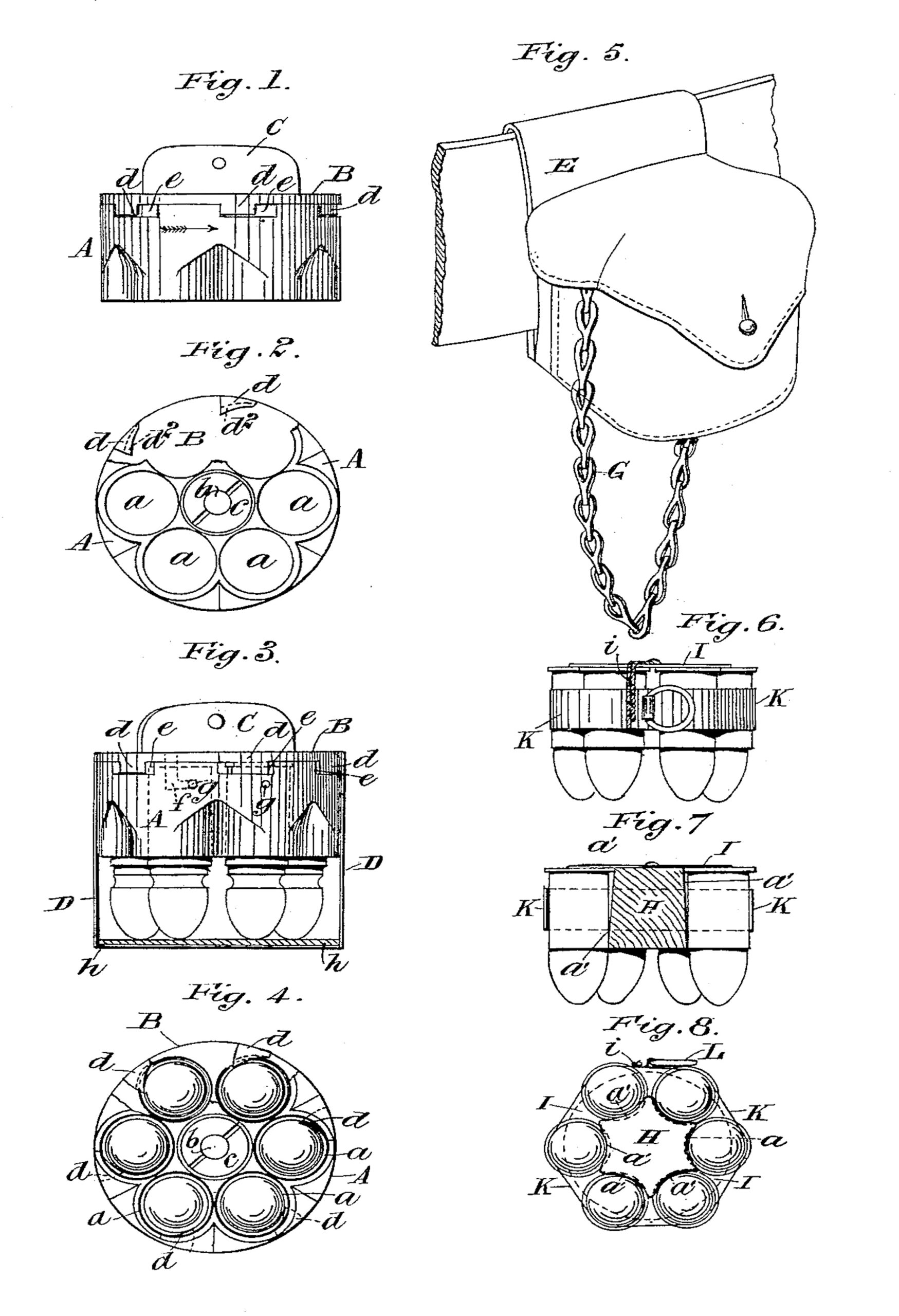
Figure 1 is a side elevation of a device constructed according to my invention for simultaneously loading with cartridges all the chambers of a six chambered revolver the cartridge retaining and releasing devices being shown in their unlocked or disengaging position. Fig. 2 is an end view of the device a portion — being broken away to show more clearly the cartridge retaining and releasing projections. Fig. 3 is a side elevation of the device shown inclosed in an outer casing and charged with cartridges ready for being inserted into the chambers of the revolver. Fig. 4 is an end view of the same the outer case being removed and Fig. 5 shows in perspective a pouch in which the device may be inclosed and carried on a belt ready for use. Fig. 6 is a side elevation of a modification which is simpler and less costly and which when the cartridges are released therefrom may be thrown away. Fig. 7 is a transverse section of the same and Fig. 8 an end view corresponding to Fig. 6.
Referring to Figs. 1, 2, 3 and 4, A is a metal cylinder or holder having holes or recesses a therein corresponding in number and position to the number and position of the chambers in the cylinder of the revolver to be loaded. The holes or recesses a are of slightly greater diameter than the rims of the cartridges so as to admit of the said cartridges being readily inserted therein rim foremost. To one end of the cylinder A is secured by a stud or bolt b a plate B which constitutes or forms a bottom to the holes or recesses a. The stud or bolt is fast on the plate B and passes through a hole in the center of the cylinder A and is secured by nuts c which enter a recess in the opposite end of the cylinder, the bolt b forming an axis on which the plate B can turn. On that side of the plate B which is adjacent to the end of the cylinder and near the peripheral edge of the said plate are segmental projections d one for each hole a in the cylinder which projections enter and can slide in recesses a in the end of the cylinder A. These projections are under cut as shown by dotted lines at d2 so as to engage the rims of the cartridges as shown in Fig. 4. The plate B is provided on its outer side with a projection C by means of which the plate may be turned on its stud or axis b.
To charge the device with cartridges the plate B is turned so as to bring the projections d against the ends of the recesses e in the cylinder as shown in Fig. 1. A cartridge is then placed in each of the holes or recesses a the cartridges being inserted base foremost. The bases of the cartridges then rest on the plate B and by turning the plate B in the direction of the arrow in Fig. 1 by means of the projection C, the segmental projection d will engage the rims of the cartridges and retain them in position in the holes or recesses a as shown in Figs. 3 and 4.
To load the revolver with the cartridges contained in the cylinder or holder the noses or bullet ends of the cartridges are inserted in the chambers of the revolver and the plate B of the holder turned by means of the projection C in the reverse direction to that indicated by the arrow in Fig. 1 thereby disengaging the projections d from the rims of cartridges which cartridges will then simultaneously enter all the chambers and thus fully load the revolver ready for firing.
The cylinder or holder A when charged with cartridges may be inclosed in an outer case until required for use as shown in Fig. 3 the said case D having bayonet slots f in the side to engage with studs or projections g on the cylinder. When in position in this outer case the ends of the bullets bear on the interior of the bottom of the said case which bottom may be covered with leather or other soft material as shown at p. To cause the studs g to engage with the bayonet slots f the cylinder or holder is turned in the case D by means of the projection C the horizontal portion of the bayonet slots extending from the vertical portions thereof in the direction in which it is necessary to turn the plate B to release the projections d from the rims of the cartridges so that should the cartridges be released from the projections d by the act of fixing the cylinder in the case D the said projections will again engage the rims of the cartridges when turning the cylinder or holder in the direction to remove it from the ease so that on removing the cylinder or holder from the case the cartridges will be removed with it.
For convenience of carrying the charged cylinders or holders a pouch such as is shown in Fig. 5 is provided for the cylinder or holder such pouch having a loop H or other convenient means by which to connect it to a waist belt or in other suitable position. Each pouch may have the case D secured therein by rivets or otherwise and to prevent the cylinder or holder from being lost it may be attached to the pouch by means of a chain G or a wire cord or the like one end of the said chain or the like being connected to the projection C and the other end to the bottom of the pouch so that when the cartridges are released from the holder and passed into the chambers of the revolver the holder although it may be allowed to fall from the hand will remain connected to the pouch.
The arrangement illustrated in Figs. 6, 7, and 8 shows a simple and inexpensive loading device which may be thrown away when the cartridges have been released and passed into the revolver. This loading device consists of a block H preferably of light material such for example as wood or ebonite and having recesses a’ for the reception of the cartridges. These recesses incline or are tapered as shown in Fig. 7 each cartridge having a bearing at one end of the recess and the edge of the rim of the cartridges having a bearing at the opposite end of the recess so that the cartridges when secured to the holder are parallel with each other. To one end of the block H is fixed a thin disk of metal against which the bases of the cartridges bear when placed in position in the recesses a’. The cartridges are held in position in the recesses a by a strip or band K preferably of thin metal which may be passed over or around the cartridges when placed in position in the recesses a’ with their bases on the disk I. One end of the strip or band K is connected by a cord i to the disk I and to the other end is secured a loop or ring L or an additional length is left projecting and the two ends may be connected together (by solder if the strip be metal). The ends of this strip or band may be connected together when passed round the cartridge or they may be previously connected to form endless bands or rings to slip onto the cartridges when placed in position in the recesses a’ and secured to the disk I by the cord i as shown in Fig. 6. To load the revolver the bullet ends of the cartridges secured in the holder are introduced into the chambers of the revolver and then the strip or band is detached by pulling the ring or loop L whereupon the cartridges being released will enter the chambers of the revolver the whole of the chambers being thus simultaneously loaded ready for firing.
My improved quick loading devices hereinbefore described are essentially suitable for the use of mounted soldiers as the chamber and barrel of the revolver when open can be conveniently held by the bridle hand without interfering with the reins, and the loading device be manipulated with the other hand.
Having now particularly described and ascertained the nature of my said invention and in what manner the same is to be performed, I declare that what I claim is—
1. In apparatus for loading the chambers of revolvers or like fire-arms the combination with a cylinder or holder for the reception of cartridges, from which the latter are fed to the fire arm to be loaded of a rotatable plate or cover secured to said cylinder or holder and means for rotating said plate or cover to different positions to lock or release the cartridges in said cylinder or holder, substantially as described.
2. In apparatus for loading the chambers of revolvers or like fire arms the combination with a cylinder or holder having chambers or recesses for the reception of cartridges, corresponding in number with, and from which the cartridges are fed to the chambers in the revolver to be loaded, of a plate or cover secured to one end of the cylinder or holder and having under-cut projections thereon to ep gage the rims of the cartridges when in position in the holder; and means for partially rotating the cover plate to cause the projections to engage or disengage as required, the rims of the cartridges substantially as hereinbefore described.
3. The combination with the cylinder or holder for the cartridges and a rotatable plate or cover secured to one end of said cylinder or holder and adapted to be rotated in opposite directions to respectively lock the cartridges in said cylinder or holder and release the same, of a ease for said parts having a bayonet slot therein and a stud on the cylinder or holder adapted to engage said slot for securing the case, said stud and slot being so arranged that the movement required to disengage the same is in a direction which insures the locking of the cartridges in the cylinder or holder by the plate or cover, substantially as described.
In testimony whereof I have signed my name to this specification in the presence of two subscribing witnesses.
A. J. WATSON.
Witnesses:
DENONETT INOSKERJN,
H.C. C. M. Office, Mean Meer.
SHANKER DOSS,
Asst. Clerk C. M. Office, Mean Meer.