
US 511406
UNITED STATES PATENT OFFICE.
HOMER M. CALDWELL, OF WORCESTER, MASSACHUSETTS.
REVOLVER.
SPECIFICATION forming part of Letters Patent No. 511,406, dated December 26, 1893.
Application filed May 6, 1893. Serial No. 473,224. (No model.)
To all whom it may concern:
Be it known that I, HOMER M. CALDWELL, a citizen of the United States, residing at Worcester, in the county of Worcester and State of Massachusetts, have invented a new and useful Improvement in Revolvers, of which the following, together with the accompanying drawings, is a specification sufficiently full, clear, and exact to enable persons skilled in the art to which this invention appertains to make and use the same.
My present invention relates to the peculiar construction, arrangement and operation of the trigger, sear and hammer mechanism; the object being to simplify the construction of double-action lock mechanism in revolvers, and to provide a structure in which the sear will effect a rebound action of the hammer in the peculiar manner explained, the particular subject matter claimed being hereinafter definitely specified.
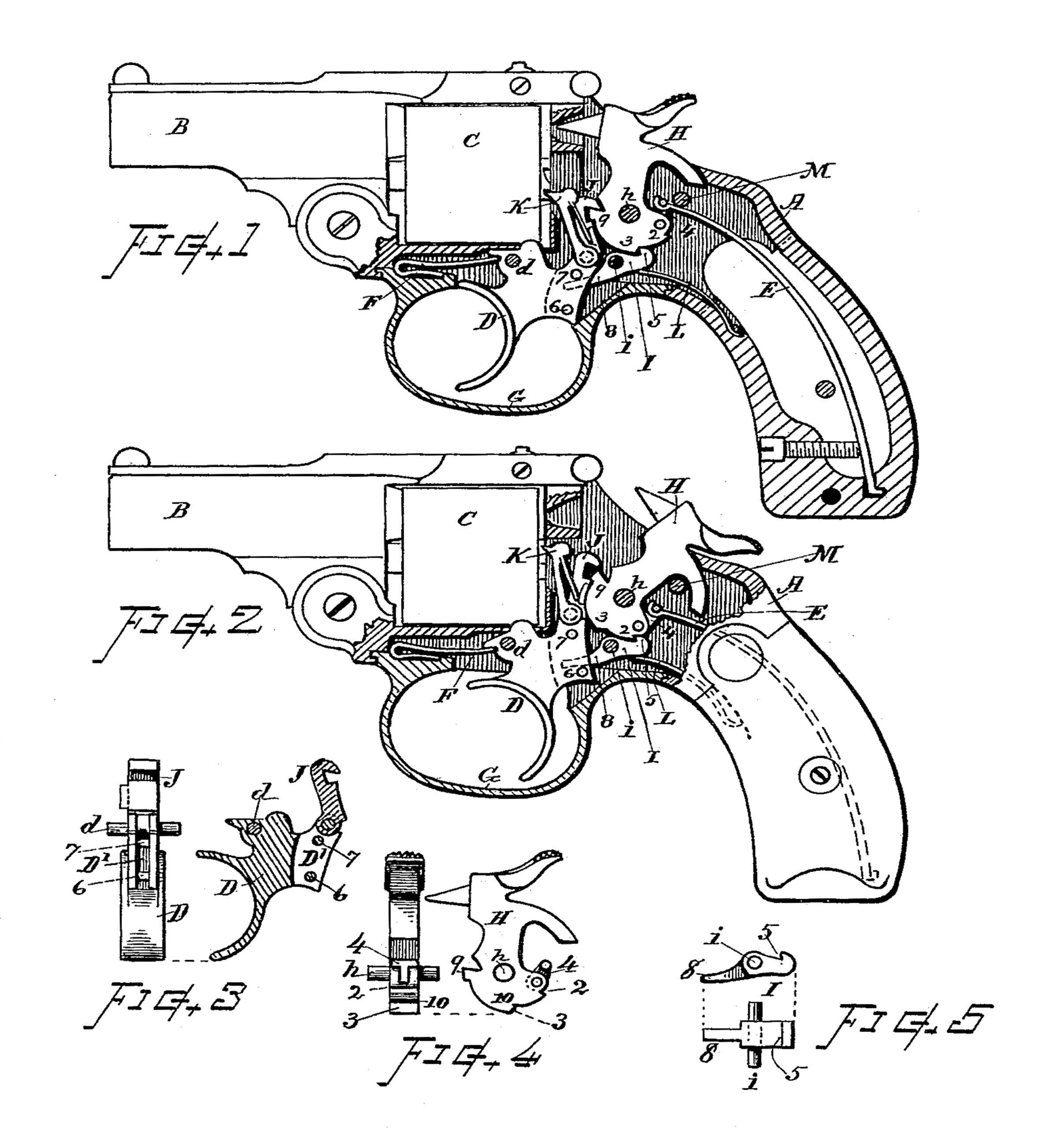
In the drawings, Figure 1 is a sectional view of a revolver illustrating my invention with the hammer at the position of rebound. Fig. 2 is a sectional view showing the hammer at full cock, and the trigger and other parts at the position occupied at the instant before discharge. Fig. 3 shows the trigger and lifter separately in rear view and in section. Fig. 4 show the hammer separately in rear and side view, and Fig. 5 shows the combined sear and rebounder separately in side and top views.
Referring to parts, A denotes the frame; B the barrel; C the revoluble cylinder; D the the trigger; E the main spring; F the trigger-spring; G the guard; H the hammer; I the sear and rebounder; J the hammer-lifter; K the cylinder-actuating pawl, and L the
sear-spring.
In my invention the hammer H is made in the form shown, with its tumbler or lower end provided with a notch 2 at the rear part, and with an inclined shoulder 3 at the bottom. The hammer is pivoted on the pin or bolt h to swing in usual manner either by the movement of the hammer lifter J, or by thumb cocking, and is thrown forward for the discharge of the cartridge by the action of the main spring E which is coupled to the rear part of the hammer-tumbler by the well known yoke 4, as indicated. A stop pin M is arranged in the frame for arresting the movement of the main spring before the hammer reaches the limit of its throw, for a purpose more fully hereinafter explained.
The trigger D is pivoted on the fulcrum-pin d in the usual manner, and is furnished with a vertical, backwardly open space or recess D’ in its rear part. (See Fig. 3.) The hammer-lifter J and cylinder-actuating pawl K are pivoted to the upper rear arm of the trigger for operating the hammer and cylinder in the usual manner as the trigger is pulled backward. The trigger-spring F is of well known kind and normally swings the trigger forward by pressing upward beneath the forwardly projecting lug upon the front of the trigger, as will be fully understood. Two pins 6 and 7 are inserted through the rear part of the trigger, which pins extend transversely across the recess or space D’, one at the lower part and one near the upper part thereof, as shown in section on Fig. 3.
The combined sear and rebounder I is fulcrumed on a pivot i fixed in the frame in rear of the trigger and below the hammer. Said part I is formed as shown in Fig. 5, with a forwardly directed hook or detent 5 on the upper part of its rear end, and with a forwardly projecting arm or portion 8 that extends into the backwardly open slit D’ within the rear part of the trigger, and engages with the pins 6 and 7 by which the arm 8 is raised or depressed accordingly as the trigger is swung to backward or forward position. The sear-spring L, which can be of any well known kind, presses upward on the rear end of the piece I and normally maintains the detent 5 in contact with the hammer tumbler.
The general structure of the revolver otherwise than in the specially improved parts specifically described can be of the usual or any suitable form.
The operation is as follows: When the hammer is cocked the detent 5 engages the notch 2. (See Fig. 2.) By further backward pull on the trigger the pin 6 engages with and lifts the arm 8, thereby throwing the detent from the notch and releasing the hammer. (The lifter J becomes disengaged from the lug 9 before the notch 2 engages the sear.) The hammer is then thrown down by. the action of the main spring. Said spring strikes the stop M and its action is thereby arrested before the hammer reaches its limit of movement, thus leaving the hammer free from pressure when it has completed its stroke; then as the trigger swings forward the pin 7 engages the arm 8 depressing it and causing the detent 5 to swing upward against the inclined shoulder surface 3 on the bottom of the hammer, and the action of this detent moving upward on said incline 3 causes the rebound of the hammer to the position shown in Fig. 1. Thus the part I, in combination with the trigger having the recess and pins therein, and the hammer having the inclined shoulder 3, serves the double purpose of a sear and a rebounder. In any instance, if desired, the hammer can be provided with a notch 10 at the upper end of the inclined surface 5, as shown on Fig. 4, so that the point 5 of the sear I will catch on and positively hold the hammer from being forced down, as might be otherwise possible by pressure sufficiently great to react the trigger spring and sear spring.
I claim as my invention herein, to be secured by Letters Patent—
1. The pivoted sear having the hook or detent on the upper part of its rear end and the forwardly projecting arm at its front, as described; in combination, with the trigger having the backwardly open recess, into which said arm extends, with the transverse pins disposed therein, one at the lower part and one near the upper part of said recess, and the hammer having its tumbler fitted with a notch at its rear part and the inclined shoulder at its bottom, for engagement with said sear, substantially as set forth.
2. The combination in a revolver, of the hammer having the sear-notch 2 and inclined rebound shoulder 3, the trigger recessed in its rear part with transverse pins 6 and 7 at the upper and lower parts of said recess, the sear and rebounder pivoted in the frame below the hammer, its arm 8 extending into the recess of the trigger between said pins, and its detent 5 engaging the notch and shoulder on the hammer, the main spring, the mainspring-stop adapted to arrest the action of said main spring within the limit of the hammer movement, and suitable springs for the sear and trigger, all substantially as and for the purpose set forth.
Witness my hand this 1st day of May, A. D. 1895.
HOMER M. CALDWELL.
Witnesses:
CHAS. H. BURLEIGH,
ELLA P. BLENUS.