
US 37091
UNITED STATES PATENT OFFICE.
A. T. FREEMAN, OF BINGHAMTON, NEW YORK.
IMPROVEMENT IN REVOLVING FIRE-ARMS.
Specification forming part of Letters Patent No. 37,091, dated December 9, 1862.
To all whom it may concern:
Be it known that I, A. T. Freeman, of Binghamton, in the county of Broome and State of New York, have invented certain new and useful Improvements in Revolving Fire-Arms; and I do hereby declare that the following is a full, clear, and exact description of the same, reference being had to the accompanying drawings, forming part of this specification, in which-
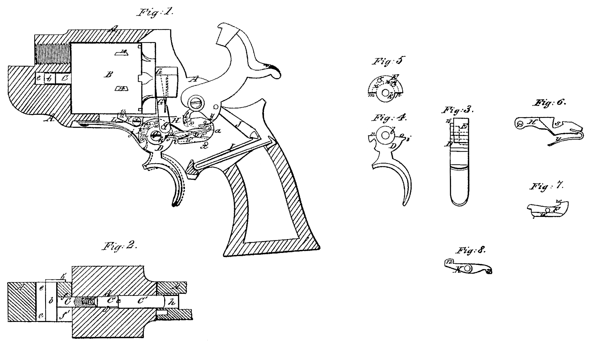
Figure 1 is a vertical longitudinal section of the frame of a revolver and a side view of the cylinder and all parts of the lock; Fig, 2, a, horizontal section, of the frame and cylinder, and a top view of the cylinder axis-pin, representing the latter partly in section. Fig. 3 is a front view of the trigger and its appendages. Figs. 4 and 5 are side views of the two portions of the trigger separated from each other. Fig. 6 is a side view of the notched link which connects the trigger with the hammer. Fig. 7 is a side view of the sear. Fig. 8 is a side view of the cylinder-locking dog.
Similar letters of reference indicate corresponding parts in the several figures.
This invention consists in a certain novel construction of and mode of applying the cylinder axis-pin, whereby facility is afforded for removing and replacing the cylinder without any danger of losing the pin.
To enable others skilled in the art to make and use my invention, I will proceed to describe its construction and operation.
A is the frame, made substantially of the usual form, and B is the cylinder, arranged within the frame A in the usual manner.
C C’ is the axis-pin, composed of two separate pieces to enable it to be so inserted in the central bore of the cylinder that while it fits loosely therein it cannot drop out in either direction when it and the cylinder are removed together from the frame. The rear piece, C’, is screwed into the front piece, C, as shown at a in Fig. 2, and when the two are screwed together they are equivalent to a solid pin. The front piece, C, is made with a T-head, b, which is no thicker than the rest of that portion of the pin, but long enough to extend all across the frame, and to protrude on the right-hand side thereof; and at the right-hand end of the said head there is a tongue, b’, Fig. 2, which extends backward a short distance parallel with the pin. The back piece, C’, is made with a shoulder, c, and the portion in front of the a shoulder, c, and the portion in front of the a shoulder, c, and the portion in front of the portion in rear of the said shoulder, which is also cylindrical, is of larger diameter. The front portion of the central bore of the cylinder B is made of a size to fit easily upon the smaller part of the pin, and the rear portion of the said bore of a size to fit the larger part of the pin, and a shoulder, d, is thus formed around the said bore. The two pieces C and C’ are inserted into the cylinder separately from opposite ends, and screwed tightly together after they have been inserted, and when they are together the head b prevents the pin from being drawn out from the cylinder in a backward direction, and the shoulder c pre vents it from being drawn out in a forward direction; but the distance between the said head and shoulder is such as to permit the pin to slide some distance longitudinally within the cylinder. When the cylinder is in its place, as shown in Figs. 1 and 2, the rear portion of the pin is received in a bearing, h, which is bored in or through the back part of the frame A, and the front portion in a bearing, f, provided for it in the front part of the frame.
Immediately in front of the front bearing a slot, e, is provided in the frame for the reception of the head b of the pin, such slot being long enough to permit the pin to slide forward far enough to remove it from the rear bearing, and the front bearing is open on the left-hand side of the frame, as shown at f’ in Fig. 2, to allow the pin to be withdrawn in a direction lateral to the frame. To insert the cylinder into its place in the frame in proper relation to the barrel, the pin is drawn forward as far as permitted by the shoulders c d, which is far enough to bring its rear end within or flush with the cylinder, and the cylinder and pin are then inserted into the frame from the left hand side; the head passing through the slot e, and the portion of the pin in front of the cylinder passing through the opening f’ to the front bearing, f. When the pin arrives in the front bearing it is pushed backward through the cylinder into the rear bearing, and by that means the tongue b’ is caused to pass outside of the portion of the frame in rear of the slot e, as shown in Fig. 2, and the pin is thereby prevented from being drawn out through the opening f’, and the cylinder is thus secured in the frame.
A small spring (not shown) may be applied in front of the pinto hold it back in the above-de scribed position. When it is desired to take out the cylinder the pin is drawn forward far enough to withdraw its rear end from the rear bearing, h, and to bring the extremity of the tongue b’ past the rear end of the slot e, and the cylinder and pin are then drawn out through the left-hand side of the frame.
D E is the trigger, made of two pieces, which are shown separately in Figs. 4 and 5, and combined in Figs, 1 and 3. The piece D does not differ very materially from the trigger of an ordinary fire-arm having the usual finger piece, being arranged to work in the usual manner upon a fixed pin, g, being formed with a heel, i, to operate upon the sear F, and having applied to it a spring, j, which tends to throw up the heel and throw forward the finger piece. The upper piece, E, is of semicircular form, and arranged to work upon the same pin g by being made with a circular joint-cheek, k, corresponding with a circular cheek, l, on the piece D, the cheeks being countersunk on opposite sides to let each drop into the other piece and bring the sides of D and E flush with each other, as shown in Fig. 3. The two pieces are so formed at m n o p in front and behind their joint-cheeks k l that when they touch each other at m n in front they are separated but a short distance at o p behind, as shown in Fig. 1, and vice versa, so that each is allowed but a trifling movement independent of the other upon the pin g. The heel i on the lower piece projects a short distance beyond the upper piece, D, which never interferes with the sear. The upper piece, D, has the revolving dog G attached to its rear part by a pin, q, and has also attached to its front part, by a pin, r, the notched link H, through which it is made to effect the cocking of the hammer by the pull of the trigger, and which is represented separately in Fig. 6. This link H. works in a mortise in the piece E. It has provided in it a notch, s, to receive a tooth, t, provided on the lower part of the tumbler or hammer-butt, which has also provided in it the usual notches, 9, for full-cock, and 10 for half-cock, the said tooth being formed by making a recess, t’, in the left-hand side of the hammer. The said link H has also attached to it a spring, u, which presses upon a ledge, u’, provided all along the left-hand side of the sear; and this spring tends to press the link upward toward the tumbler or hammer-butt, and to depress either the front or rear end of the sear, according as it bears upon the ledge u’ at a point in front or in rear of the pin v, upon which the sear works. The sear is in the form of a lever, the front end of which is so situated as to be operated upon by the heel i’ of the trigger, and the rear end of which has formed upon it the hook w, for entering the cock and half-cock notches in the tumbler or hammer-butt. When the hammer is down the tooth t is deep in the notch s, and the point of the spring u presses upon the sear in rear of the pin v, and so keeps the hook w down clear of the tumbler, the sear then resting upon a fixed stop-pin, x, secured in the frame, and the trigger is thrown far forward of the position shown in Fig. 1, which represents the arm at full-cock, and the surfaces m n of the two parts of the trigger are in contact, and the surfaces op at a short distance apart. To cock the piece for deliberate firing the hammer is drawn back by the thumb, and its tooth t is caused to carry forward the link H, and by so doing causes the said link to give the trigger a movement similar to what would be produced by drawing back the finger-piece of the latter, except that the surfaces m n remain in contact, and this movement of the trigger causes the dog G to move upward and produce the necessary revolution of the cylinder, the dog acting upon a ratchet on the rear of the cylinder, as in other revolvers.
Almost at the commencement of the above described movement of the link H the point of the spring u passes the pin v, and so by pressing upon the sear in front of the said pin causes the hook w of the sear to press against the tumbler, so that it may drop into the half-cock notch 10, in case the hammer is not brought back to full-cock, or into the cock-notch if the hammer is brought to the position of full-cock. As the hammer is approaching the position of full-cock a cam-like projection, y, provided on the tumbler, is caused to press down the rear end of the link H so far that the back edge of its notch s is clear of the tooth t, and the said link will offer no obstruction to the fall of the hammer. The hammer will remain cocked until the trigger is pulled, when the piece D turns on the pin g, while the piece E is held forward by the link H, as shown in Fig. 1, and the heel i is brought into action on the sear, which is thus removed from the cock-notch, and the hammer is allowed to be thrown down or forward by the mainspring I, which is connected with it by the stirrup J, and applied in a Well-known manner.
If it is desired to fire quickly by the action of the trigger alone, without cocking, the pull on the trigger first moves the piece D only till the surface o is brought into contact with the surface p, after which the piece E moves with the piece D, and by drawing forward the link H and carrying upward the dog G produces both the cocking of the hammer and the rotation of the cylinder. By the time the hammer has arrived at full-cock the cam y has depressed the rear end of the link H so far that the rear edge of the notch s is brought below the point of the tooth t, as before described with reference to cocking by the hammer itself, and previously to this the heel i of the trigger has come into contact with and raised the front end of the sear and so depressed the hook of the latter that it will not catch in the full-cock notch 9, and hence the hammer is allowed to be thrown down or forward by the mainspring as soon as the back edge of the notch s has cleared the tooth t. By releasing the finger piece of the trigger from the pressure of the finger and allowing it to be brought forward by the spring j after the fall or downward movement of the hammer and afterward pulling it back again the fire can be rapidly repeated
It will be understood that the operation of cocking the hammer and deliberately firing and that of firing repeatedly by-pulling the trigger are permitted by the construction of the trigger of the two parts D and E, having movements to some extent independently of each other, as described, the heel of the trigger in the latter case being permitted to free the sear from the tumbler while the hammer is moved to the position of full-cock, but being permitted to do so in the former case.
K is the cylinder-locking dog, made of the form of a lever having a tooth, 12, on the upper side of its front end, and a projection, 13, on the under side of its rear end. This dog or lever is arranged to work below the cylinder on a fixed pin, x, which secures it in a slot in the bottom of the frame A.
L is a spring applied within the frame A, below the front part of the dog to press it up ward toward the cylinder, in the exterior periphery of which there are provided for its reception a series of equidistant notches, 14, corresponding in number with the chambers and occupying such positions relatively to the chambers that when one of the latter is opposite to the barrel one of the said notches is opposite to the tooth 12 of the dog. The projection 13 on the rear end of the dog is situated over a cam, 15, Figs. 3 and 5, that is formed on the right-band side of the piece G of the trigger. The periphery of this cam 15 is of the form of an arc concentric with the pin g, with a notch, 16, for the reception of the projection 13 on the rear end of the dog. While the hammer is cocked or the finger-piece of the trigger is held back and a chamber of the cylinder is opposite the barrel, and a notch, 14, opposite the tooth 12 of the dog, the notch 16 of the cam is opposite the projection 13 of the dog, and the spring Lu is allowed to force the tooth 12 into the notch 14 and lock the cylinder by the said projection 13 dropping into the said notch 16; but when the finger-piece of the trigger is allowed to move forward the projection 13 is caused to ride up onto the top of that portion of the cam in front of the notch, which holds it up so high that the tooth 12 is depressed to a position in which it leaves the cylinder unlocked and allows it to rotate. The entrance to the notch 16 is rounded in such manner that it allows the projection 13 of the dog to slip in and out easily.
Instead of making the cylinder axis-pin of two pieces, in the manner described, the piece C being of the full length required for the pin, and the second piece consisting merely of a collar driven or secured on to the rear part of C, after the insertion of the latter into the cylinder the front end of this collar forms the shoulder c and limits the longitudinal movement of the pin.
What I claim as my invention, and desire to secure by Letters Patent, is—
The cylinder axis-pin constructed of two pieces, C C’, with a shoulder, c, a T-head, b, and a tongue, b’, and applied in combination with the cylinder and the frame of the fire-arm, substantially as herein specified.
A.T. Freeman.
Witnesses:
Pitt Hoard,
S. Floyd Hoard.