
US 37329
UNITED STATES PATENT OFFICE.
FORDYCE BEALS, OF NEW HAVEN, CONNECTICUT.
IMPROVEMENT IN RAMMER-CONNECTIONS for REVOLVING FIRE-ARMS.
Specification forming part of Letters Patent No. 37,329, dated January 6, 1863.
To all whom it may concern:
Be it known that I, Fordyce Beals, of the city of New Haven, in the county of New Haven and State of Connecticut, have invented a new and useful Improvement in Revolving Fire-Arms; and I do hereby declare that the following is a full, clear, and exact description of the same, reference being had to the accompanying drawings, forming part of this specification, in which—
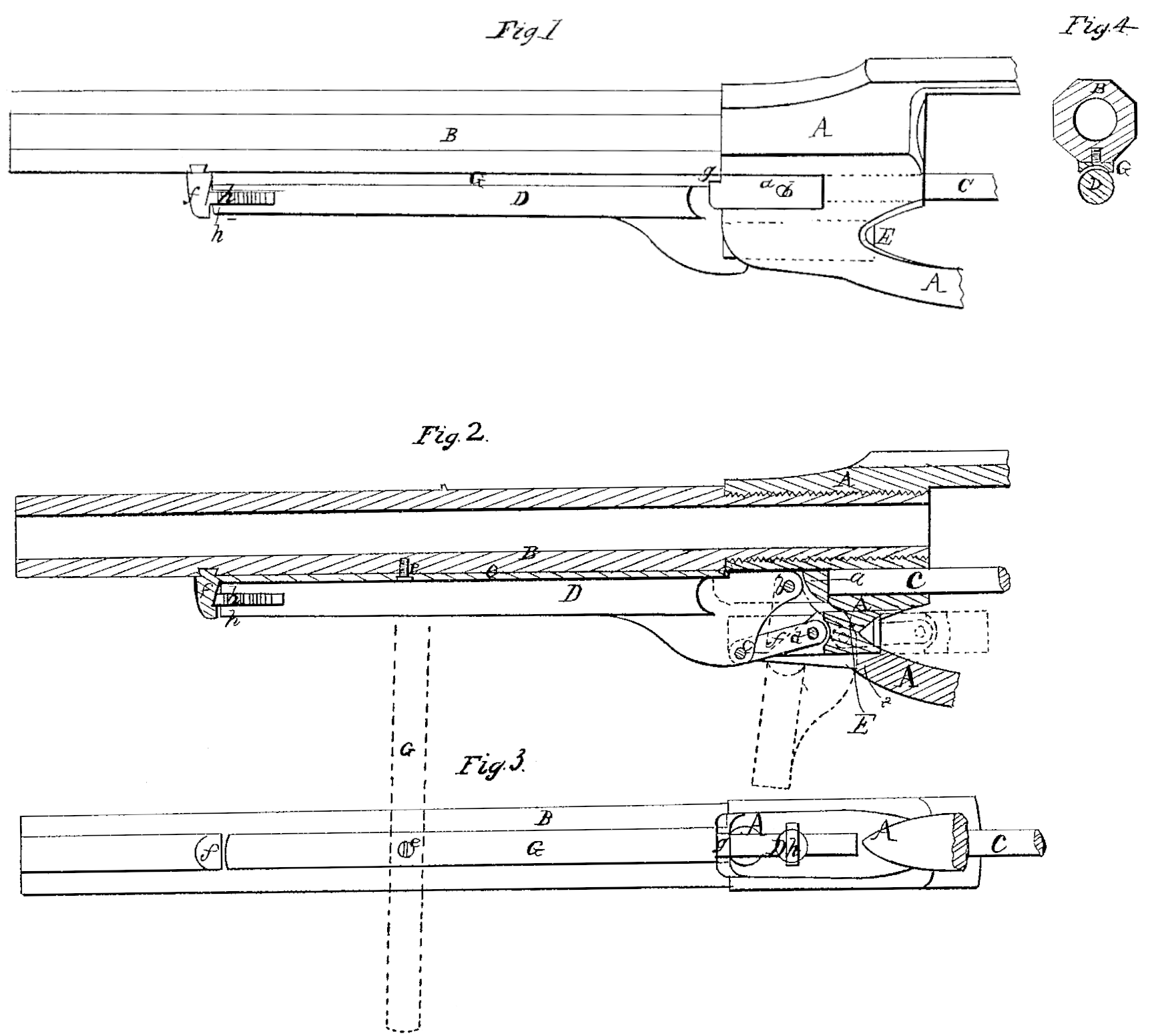
Figure 1 is a side view of the barrel, part of the frame, the rammer, and the cylinder axis-pin of a revolving pistol, and the device for securing the said pin in place, which constitutes my invention. Fig. 2 is a central longitudinal vertical section of the same. Fig. 3 is an under side view of the same. Fig. 4 is a transverse section of the same.
Similar letters of reference indicate corresponding parts in the several figures.
To enable others skilled in the art to make and use my invention, I will proceed to describe its construction and operation.
A is the front portion of the frame, and B is the barrel.
C is the cylinder axis-pin, passing through the front portion of the frame and through the cylinder and entering the rear portion of the frame or recoil-shield in the usual manner, and having its head at fitted into a transverse mortise in the front part of the frame to prevent it from turning.
D is the rammer-lever, attached to the head a by a pin, b, which constitutes the fulcrum.
E is the rammer, connected with the lever by a link, f’, and two pins, c d.
G is the bar or rib, which constitutes the principal feature of my invention, attached to the bottom of the barrel B by a pivot-screw, e, at a point between the front of the frame and the stud f, which locks the rammer-lever D. This bar or rib is just long enough to abut against the stud f and the head a of the pin C, and its end is formed With a small tongue, g, to enter a rabbet provided in the upper part of the pin. When the said bar or rib is parallel with the barrel the pin C cannot be withdrawn, but is held securely in place. The under side of the said bar or rib is made concave in a transverse direction, as shown in Fig. 4, to form a bed or seat into which the lever D, which is of round form in its transverse section, can fit snugly when it is locked by the entrance of its spring-bolt h into the notch in the stud f, in which position it is thus caused by the aforesaid concave form of the under side of the rib or bar G to secure the said rib or bar firmly against any lateral displacement by a blow or pressure.
When it is desired to withdraw the pin C for the purpose of taking out the cylinder the lever D is first moved down to the position shown in Fig. 3, and in red outline in Fig. 2, and the rib or bar turned on the pivot e to a transverse position, as shown in dotted outline in Fig. 3. By then pressing back the lever the under portion of the latter is brought into contact with the edge i of the slot provided in the frame A for the lever to work in, as may be understood by reference to the representation of the lever in red outline in Fig. 2, and the point i then becomes a fulcrum on which the lever acts to start the pin C, after which it can be drawn out easily by a direct pull of the lever.
By the employment of the rib or bar G to secure the pin C, when the said pin has the rammer-lever connected with it, the said pin, being secured in front of the connection of the lever, and thus not being subjected by the lever to any strain, does not require to be any stronger than is necessary for the support of the cylinder, and its greater size is not made the cause of weakening other parts of the arm or of producing unnecessary friction.
The pivot e, upon which the bar or rib turns, instead of being arranged at a distance from the stud f, may be attached directly to or formed upon the said stud itself, and the operation of the said rib or bar will then be essentially the same as when the pivot is arranged in the manner first mentioned.
What I claim as new, and desire to secure by Letters Patent, is—
The combination of the pivoted bar G, constructed as set forth, with the axis-pin C and the rammer-lever D, substantially in the manner herein shown and described.
FORDYCE BEALS.
Witnesses:
Charles Ives,
John S. Fowler.