
US 37693
UNITED STATES PATENT OFFICE.
JOHN C. HOWE, OF WORCESTER, MASSACHUSETTS.
IMPROVEMENT IN REVOLVING FIRE-ARMS.
Specification forming part of Letters Patent No. 37,693, dated February 17, 1863.
To all whom it may concern:
Be it known that I, John C. Howe, of Worcester, in the county of Worcester and State of Massachusetts, have invented certain new and useful Improvements in Revolving Fire-Arms; and I do hereby declare that the following is a full, clear, and exact description of the same, reference being had to the accompanying drawings, forming part of this specification, in which—
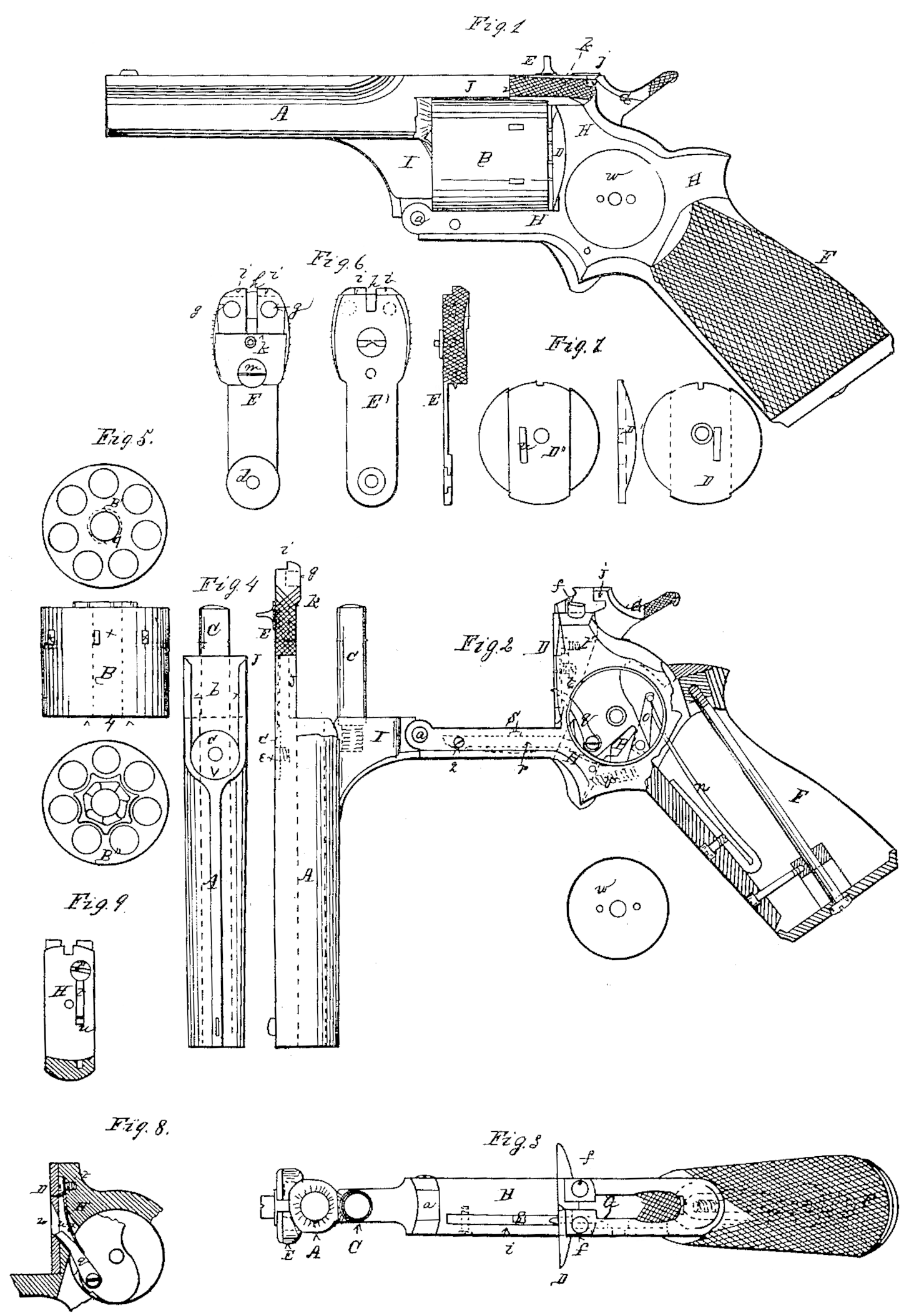
Figure 1 is a side view of a pistol with my improvements, representing it in condition for use. Fig. 2 is a side view, representing it with the cylinder-frame open and the cylinder removed, the stock partly in section, and the side plate removed to expose the lock to view. Fig. 3 is a top view corresponding with Fig 2. Fig. 4 is a top view of the barrel. Fig. 5 represents side and end views of the revolving cylinder. B is the side view, B’ the front end view, and B” the back end view. Fig. 6 represents bottom, top, and side views of a spring-latch which connects and locks the barrel with the upper part of the frame, and attaches the cylinder to the barrel when the frame is open. E is the bottom view, E’ the top view, and E” the side view. Fig. 7 represents face, side, and back views of a recoil-plate, secured to the frame just back of the revolving cylinder. D is the face view, D’ is the side view, and D” is the back view. Fig. 8 is a vertical section, parallel with the length of the arm of the recoil-plate and the part of the frame in rear of it. Fig. 9 is a transverse section of the frame, taken immediately in rear of the recoil-plate.
Similar letters of reference indicate corresponding parts in the several figures.
The nature of my invention consists, first, in the employment, in combination with a cylinder-frame opening by a movement on a hinged joint arranged in front of and below the line of the axis of the cylinder, and with an axis-pin secured to the barrel, of a spring-latch so constructed and applied as to serve the two purposes of connecting and locking the barrel with the upper part of the frame, and of securing the cylinder upon the axis-pin when the barrel is disconnected from the upper part of the frame.
It consists, secondly, in so constructing the spring-latch and the hammer that when the hammer is down it aids in securing the spring-latch in its connection with the frame, and so aids in securely locking the barrel to the upper part of the frame.
It consists, thirdly, in so constructing the axis-pin and applying the same, in combination with the barrel or frame of the arm, that while remaining attached to the barrel or frame it may be employed to expel from the chambers of the cylinder the cartridge cases or shells, or other matter which may remain therein after firing the arm; and it consists, finally, in a certain mode of applying a detachable recoil-plate, in combination with the spring which keeps the revolving dog to its work, whereby the said plate, while allowing the dog to work through it, is made to aid the said spring in excluding from the lock any gases escaping at the rear of the cylinder in firing.
The barrel A is made similar to those now in use. Its form and proportions, as well as many other parts of the arm, may be varied to suit the taste of the maker.
I is a part projecting downward and at the breech of the barrel A. At the lower extremity of I is formed a joint, a, uniting the barrel with the frame, the center of which joint must be below the line of the axis of the cylinder, and may be on a line, or nearly so, with the lower line of the periphery of the cylinder when the cylinder is upon the axis-pin, the object of which joint is to connect the barrel A with the frame H, and to allow the barrel to oscillate. The joint a must be so situated that when the cylinder is properly upon its axis-pin, and contains any ammunition adapted to it or not, the oscillation of the barrel and cylinder shall not be obstructed by the recoil-plate D.
J is a part which projects from the barrel at its breech, in line with the upper’ portion of the barrel, and extends partly over the cylinder. The lower face of J is made to conform to the periphery of the cylinder. In the upper surface of J, and extending partly over the breech of the barrel, a seat (see b, Fig. 4) is furrowed, having rectangular sides, to receive and hold the spring-latch, hereinafter described. The portion of this seat marked c is countersunk to receive a corresponding projection or head upon the under side of the spring-latch. Said projection is marked d in E, Fig. 6.
The axis-pin C, (see Fig. 2.) upon which the cylinder revolves, is secured to the lower projecting part, I, of the barrel parallel with the bore of the barrel, and at such distance therefrom that as the cylinder is made to revolve its chambers will come, one at a time, in a true line or range with the bore of the barrel. The diameter, length, and form of this pin are such that it may be employed to expel from the chambers of the cylinder the cartridge cases or shells, or other matter which may remain after firing the arm. For this purpose the projecting or outer end of the pin may be finished square or with a cutting edge or shoulder.
The frame H (see Fig. 1) is similar to those in use, except the joint a, which has already been described and its uses set forth.
The recoil-plate D is made separately, of about the same diameter across its face as the cylinder, having oval flanges upon its reverse side D” projecting upon and fitting the frame, to which it is secured by a screw. It has an opening or slot, u, through which the dog q, for revolving the cylinder, works. The face or front of this plate is finished flat and smooth. It is made separately from the frame and detachable, for two reasons, one of which is that different metals may be used for it and the frame, and a better finish and more perfect working of the adjacent and associated parts may be secured; and the other is that it affords greater facility for the protection of the lock from gases. escaping at the rear of the cylinder by permitting the spring t, which presses the dog q forward against the back of the cylinder, to be arranged behind the recoil plate, and in front of the portion of the frame which supports the said plate, as illustrated in Figs. 8 and 9. This spring t works in a slot, u’, in the frame H, through which the dog q also works, the said slot being of the same width as the slot u in the recoil-plate, and the dog and the spring both fitting as snugly in the slots u and u’ as is consistent with their proper freedom of operation. The upper front part of the slot u’ is made of a form to serve as a bearing, against which the spring is secured by a screw, t’, which screws into the frame H and whose head is countersunk thereinto, so that it may be covered by the recoil-plate, as shown in Fig. 8. The slot u in the recoil-plate is thus enabled to be made shorter than the slot u’ in the frame, and made to cover a portion of the latter slot, and so the recoil-plate is made to partly cover the latter slot and in a measure to exclude the gases therefrom and the portion not so covered is closed almost entirely by the dog g and spring t fitting so snugly within it.
E is a part of the arm, which I call a “spring-latch,” by means of which it is convenient to connect and disconnect the barrel and the frame over and just back of the cylinder, so that when the barrel is disconnected or unlatched from the frame it (the barrel) may oscillate upon the joint a, and thus expose the cylinder in a manner convenient for loading and unloading.
Another feature of this improvement is that when the barrel is unlatched from the frame the cylinder is retained upon its axis-pin by means of a shoulder, k, in the spring-latch, while by lifting the spring-latch the cylinder is released from the shoulder k, and can be easily withdrawn from the axis-pin. For cavalry use this feature in the improvement is very important, as when the barrel is unlatched from the frame— or, in other words, when the arm is opened for loading— the cylinder is secured against being dropped, while yet it is easy and convenient to quickly separate the cylinder from the rest of the arm, and, if necessary to remove the cartridges, shells, or other matter from the chambers of the cylinder, the axis-pin C, as before described, is so situated and so formed as to be conveniently used for that purpose.
I will describe the spring-latch E.
d is a projecting head upon the under side of the latch, which fits into a corresponding countersink, c, (see Fig. 4.) in the upper side and near the rear end of the barrel. Through the center of d, and entering the center of c, a screw, e, (see Fig.2) connects the latch at this point firmly with the barrel. This connection matches and locks the parts together, so as effectually to resist any strain that may come upon them in the use of the arm.
From the connection at c to the end of that part of the barrel marked J the latch is formed to occupy the groove or seat b, before described, (see Fig. 4) the thickness of this part of the latch being governed by the degree of motion or spring required. At the extremity of the part of the barrel marked J the latch is formed to a shoulder on the under side, fitted so as to abut at the end of the part J, and this portion of the latch is shaped like the part J on the under side— i.e., to conform to the periphery of the cylinder. At a proper point (marked k) another shoulder. is formed on the under side of the latch, sufficient to retain the cylinder in its place when the parts are adjusted. At a proper distance back from the shoulder k the latch is provided with indentations or holders, (see g g,) to connect and disconnect with suitable parts or projections (see f f) attached to the frame, so as to conveniently latch and unlatch the barrel and frame.
h is an opening through which the hammer strikes the cartridge.
i i (see E, Fig. 6) are recessed shoulders in the end of the spring-latch, made to receive | catches or hook-formations (see j) on the hammer, so that when the hammer is down it may assist in locking or fastening the spring-latch in its connection. With the frame, the latch being only capable of being released from its connection with the frame by a directly-upward movement, and the movement of the hammer from that position being more backward than upward.
Instead of the hammer being made with catches or hook formations j, and the spring. latch being made with recessed shoulders i i, as described, the hammer may have its nose tapered in a downward direction, and the opening h in the spring-latch may be made with a corresponding downward taper, and the nose of the hammer fitting snugly in this taper-groove when the hammer is down will lock the spring-latch with the same result as is produced by the catches j and recessed shoulders i i.
m (see E) is a stop to regulate the motion of the spring-latch and to protect it from injury in use.
f f (see Figs. 2 and 3) are projections inserted into or made part of the frame to connect and disconnect with suitable recesses in the spring-latch (see g g) for fastening and unfastening the barrel and frame.
The hammer is similar to those in use, except it is provided with catches or hook formations.j, or has its nose tapering downward, as before described.
The cylinder is similar to those in use, except that the axis or center hole is made so nearly like the caliber of the chambers that the axis-pin C may be used for the purposes hereinbefore described, and the central hole is slightly enlarged at its forward end, 4, (see red dotted lines B B’,) to more freely admit the end of the axis-pin.
The lock.— G is the hammer; n, the main spring; q, the lever secured to the tumbler part of the hammer and extending upward through the opening at in the recoil-plate D, to operate against notches in the rear end of the cylinder, so as to revolve the same at each cock of the hammer, and to bring one of its chambers in line with the bore of the barrel.
o is the swivel or stirrup. v is the trigger-spring behind the trigger, (See red dotted lines.) w is the movable lock-cap. r is a stop-lever (shown by red dotted lines, see Fig. 2) situated in a groove in that part of the frame which is under the cylinder, and secured at its forward end by a screw, 2, the other end extending within the lock-case on which (last end) is formed an angular tooth. This lever is provided with a stud, s, projecting from its upper side and made to fit into the depressions or stop-holes x, Fig. 5, in the periphery of the cylinder, for the purpose of holding the cylinder when it has been revolved to the proper position for firing. This lever is pressed upward by a spring secured beneath it.
p is a fly similar to those heretofore in use. It moves on a pivot, and is placed in a recess formed in the tumbler part of the hammer. The lower end of this fly is angular, or so shaped as to operate upon the angular tooth on the end of the stop-lever, and the proportions and arrangement of the fly and stop-lever, working I together and in combination with the hammer, as described, are such that while the hammer is being drawn back to full-cock the lower end of the fly shall press upon and pass forward over the angular end of the stop-lever, causing the studs to be withdrawn at the proper time from its place in the cylinder, and while the hammer descends, as in firing the arm, the motion of the fly is reversed, and its lower end passes back over the angular end of the stop-lever without causing the studs to be wholly withdrawn from the cylinder.
In using this arm first lift the hammer G to half-cock, then, holding the arm by its handle F with one hand, take hold of the serrated edges of the spring-latch E with the thumb and forefinger of the other hand and lift the spring-latch, then press the barrel downward into the position shown in Fig. 2, when the cylinder will be in position for the introduction of fixed ammunition, or to be easily removed from its pin. To remove the cylinder from its axis-pin lift the spring-latch E until the shoulder k will allow the cylinder to pass it freely. When the cylinder is detached the axis-pin may be conveniently introduced into each of the chambers of the cylinder, so as to expel the ammunition shells, cases, or other matter which may remain after firing the arm; but ordinarily the ammunition-shells, after firing, can be taken from the chambers by the fingers without removing the cylinder.
The object of this improvement is to produce a more perfect and reliable side-arm, and one more particularly adapted for the use of mounted men.
What I claim as my invention, and desire to secure by Letters Patent, is—
1. The spring-latch E, constructed and applied to serve the two purposes of connecting and locking the barrel to the upper part of the frame, and of securing the cylinder on the axis-pin when the barrel is disconnected from the upper part of the frame, substantially as herein described.
2. So constructing the rear end of the spring-latch and the head or nose of the hammer that when the hammer is down it aids in securing the spring-latch in connection with the frame, substantially as herein specified.
3. So constructing an axis-pin and applying the same, in combination with the barrel or frame, that while remaining attached to the barrel or frame it may be used to expel from the chambers of the cylinder the cartridge cases or shells, or any other matter which may remain therein after firing, substantially as here in described.
4. Though I do not claim a movable recoil plate, I claim the combination of the detachable recoil-plate ID and the spring t, inserted in the front of the frame, and secured by a screw, t’, covered by the said recoil-plate, substantially as and for the purpose herein described.
Hartford, August 30, 1862.
JOHN C. HOWE. [L. S.]
Witnesses:
Geo. T. Thompson,
Chas. T. Hall.