
US 35404
UNITED STATES PATENT OFFICE.
AARON C. VAUGHAN, OF BEDFORD, PENNSYIVANIA.
IMPROVEMENT IN REVOLVING FIRE-ARMS.
Specification forming mart of Letters Patent No. 3540, dated May 27, 1862.
To all whom it may concern:
Be it known that I, Aaron C. Vaughan, of Bedford, in the county of Bedford and State of Pennsylvania, have invented a certain new and useful Improvement in Revolving Fire-Arms; and I do hereby declare the following to be a full and exact description of the same, reference being had to the accompanying drawings, making1 part of this specification, in which—
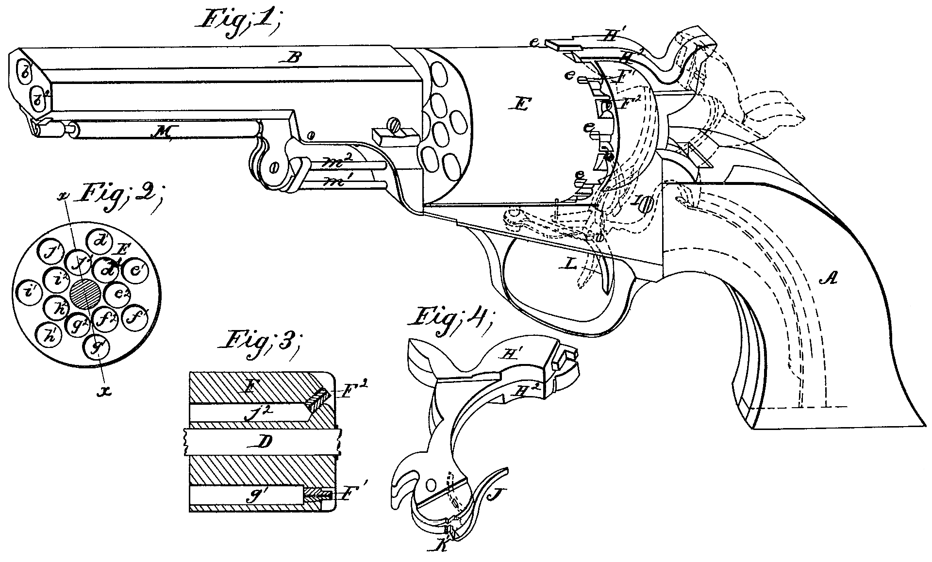
Figure 1 is a, perspective view of a pistol illustrating my invention. Fig. 2 is a front view of the revolving cylinder. Fig, 3 is a longitudinal section of the said cylinder at x x, Fig, 2. Fig.4 is a perspective view of the hammer.
Similar letters of reference in the several figures indicate corresponding parts.
The subject of my invention ix a double-barreled fire-arm having two hammers actuated in succession by a single trigger, and a revolving breech With two concentric series of chambers.
To enable others skilled in the art to make and use the said invention, I will proceed to describe its construction and operation.
A represents the stock, and B the barrel, which are connected together in customary manner by means of a bolt, C, passing through the frontend of the stationary axis-pin D, upon which the revolving many-chambered breech E turns. The barrel B is double, one bore, b^2, being on one side of and below the other, b’, as clearly shown in Fig. 1. The revolving breech E is provided with two concentric series of chambers, d’ e’ f’ h’ i’ j’ and d^2 e^2 f^2 h^2 i^2 j^2, so arranged that the chambers d’ and d^2 shall correspond at one time with the bores b’ and b^2 respectively, and the chambers e’ and e^2 shall correspond with the said bores at another time, and so on as the breech E is rotated. The nipples F’, which communicate with the outer circle of chambers, d’ e’, &c., are set in line with the axes of the said chambers. The nipples F^2, which communicate with the inner circle of chambers, d^2 e^2, &c, point obliquely outward, so that the ends of all the nipples are nearly in a, circle. This renders it more easy to apply the caps to the nipples F^2, and also places them within better reach of the hammer. The positions of the nipples of the respective chambers are clearly shown in Fig. 3.
H’ and H^2 are the hammers, the faces of which are formed to correspond with the angles of the ends of the respective nipples. The said hammers are provided with independent springs within the stock, which springs are indicated by dotted lines in Fig. 1, and are pivoted on a common axis or pin, I. The hammer H’, when elevated, withdraws the spring-stop from the holes e in the periphery of the breech, so as to permit the rotation of the barrel, and the hammer H^2 rotates the breech by means of a pivoted spring-pawl, J, taking into ratchet-teeth, as is usual with revolving fire-arms. The full-cock notches of the hammers are of common form. The half-cock notch of the hammer H^2 is made of much greater depth, as shown at K in Fig. 4, in order to catch and retain the said hammer when the hammer H’ is released as will be presently explained.
The trigger L is of common form, excepting that its head is somewhat elongated, as shown in dotted lines in Fig. 1, to adapt it to catch and retain both hammers.
The ramrod M is of the hinged kind commonly used with revolvers, but is provided with two rods, m’ m^2, to adapt it to forge the charges into both the adjacent chambers simultaneously.
The loading and capping of the piece are performed in customary manner. To cock it the hammer are raised simultaneously, in which action the hammer H’ releases the revolving breech, and the hammer H^2 rotates it the required distance, as before stated, both hammers being at full-cock and so held by the trigger. This position of the parts is indicated by red lines in Fig. 1. When it is desired to fire the pulling of the trigger withdraws it from the full-cock notches of both hammers, and the hammer H’, descending, explodes the charges of the outer chambers, which may be in position therefor; but by reason of the greater depth or projection of the half-cock notch of the hammer H^2 the trigger catches near the edge or extremity thereof, and so hold the hammer as long as desired. Upon again pulling the trigger the hammer H^2 is released and descends, exploding the charge in the chamber of the inner circle. By again raising the hammers a second pair of chambers are presented to the action of the hammers, and so on.
It will be observed by examination of Fig. 1 of the drawings that the respective nipples of each pair are separated by a thin plate of metal, while between the successive pairs a space or partition of considerable width exists.
The arm, when charged, may be safely carried by resting the right-hand hammer, H’, upon the left-hand nipple, F^2, and the left-hand hammer, HI, on the wide partition to the left thereof. In this position of the parts the breech is securely held against rotation, the hammer H^2 is not in contact or within reach of either nipple, and the hammer H, by reason of the angle of its face and that of the nipple, cannot be forced into such contact with the top of the latter as to endanger an explosion by ab accidental blow.
Having thus described my invention, what I claim therein as new, and desire to secure by Letters Patent, is—
1. A revolving breech, B, having two concentric circles of chambers provided respectively with axial nipples F’ and oblique nipples F^2, for the objects stated.
2. A double barrel and a revolving breech having two concentric series of chambers, in combination with two hammers actuated in succession by a single trigger, and one of them employed to discharge an outer and the other an inner chamber, substantially as set forth.
The above specification of my improvement in revolving fire-arms signed this 18th day of February, 1862.
AARON C. VAUGHAN.
Witnesses:
Octavius Knight,
James H. Gridly.