
US 35657
UNITED STATES PATENT OFFICE.
JOHN H. WICKERS, OF WORCESTER, MASSACHUSETTS, ASSIGNOR TO LUCIUS W. POND, OF SAME PLACE.
IMPROVEMENT IN REVOLVING FIRE-ARMS.
Specification forming part of Letters Patent No. 35,657, dated June 17, 1862.
To all whom it may concern:
Be it known that I, John H. Vickers, of Worcester, in the county of Worcester and State of Massachusetts, have invented a new and useful Improvement in Revolving Fire-Arms; and I do hereby declare that the following is a full, clear, and exact description of the same, reference being had to the accompanying drawings, forming a part of this specification, in which—
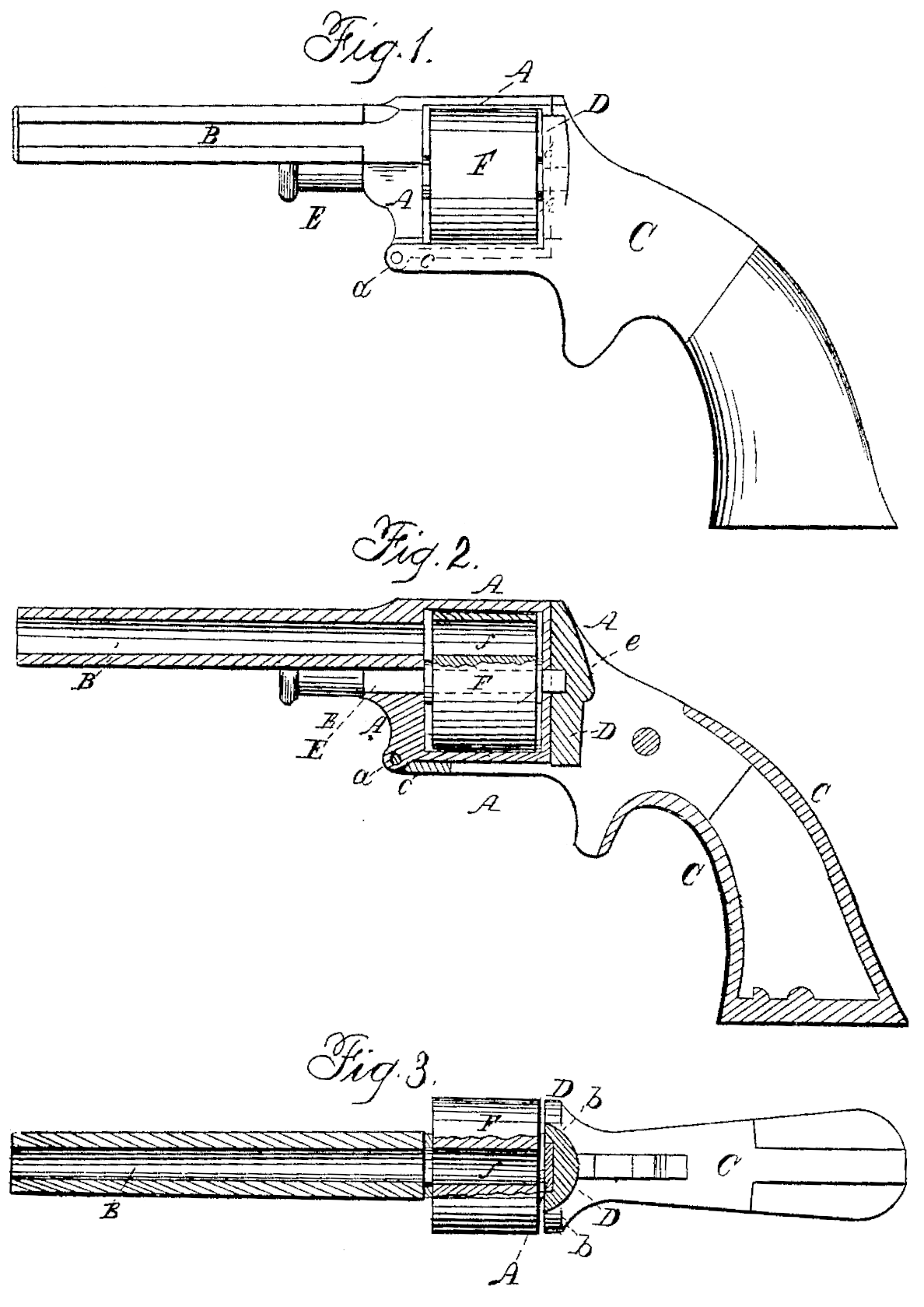
Figure 1 is a side view of a pistol with my improvement. Fig. 2 is a longitudinal central section of the same. Fig. 3 is a top view of the same, partly in section.
Similar letters of reference indicate corresponding parts in the several figures.
This invention consists in the employment, in a revolving fire-arm, of a continuous frame rigidly attached to the barrel, inclosing the cylinder lengthwise, and pivoted to the stock in such manner as to enable the rear part to fold into the breech-piece and to form a recoil-plate independent of the breech-piece for relieving the breech-piece of the strain of the recoil, such frame allowing the cylinder and breech-piece to be separated for the introduction of the cartridges into the chambers at the rear thereof.
It further consists in so applying the cylinder axis-pin, in combination with such continuous frame, that it passes through the said frame and cylinder from front to rear thereof and enters a hole in the breech-piece in such manner as to secure or assist in securing the said frame in proper connection with the breech-piece.
To enable others skilled in the art to apply my invention to use, I will proceed to describe it with reference to the drawings.
A is the continuous frame for the reception of the cylinder, made in the same piece with the barrel B, or having the latter screwed into or otherwise rigidly attached, the said frame being just long enough for the reception of the many-chambered cylinder F and of the flanges of the metallic cartridges, which are left protruding through the rear of the chambers thereof.
C is the stock-frame, having the circular breech-piece D, which covers the rear of the cylinder, made in the same piece with it, and a portion of it extending forward from the bottom of the breech-piece, as shown at c, far enough for the connection with it of the lower front angle of the continuous cylinder-frame A by means of a pivot or hinge-joint, a. The back of the frame A, which is a little wider than the caliber of the chambers, is fitted to a groove, b, provided for its reception in the breech-piece, and the lower side of the said frame is fitted to a groove provided for it in the part c of the stock-frame.
E is the cylinder axis-pin, inserted through a hole in the front of the cylinder-frame A, through the center of the cylinder, through a hole in the rear of the cylinder-frame, and into a hole, e, in the center of the circular breech-piece. This pin, when secured in the cylinder-frame by suitable means applied near its front end, serves by its entrance into the breech-piece to secure or assist in securing the cylinder-frame to the breech-piece; but other means for securing the frame may be employed.
To insert the cartridges in the chambers f f of the cylinder, the axis-pin E is drawn forward far enough to remove its rear end from the hole e in the breech-piece D, and the barrel and stock are folded downward from the hinge-joint a to expose the rear end of the cylinder, whose chambers are open at the rear for the reception of the cartridges. When the barrel and stock are thus folded down the cylinder is free to be turned by hand upon the axis-pin. After the chambers, have all been loaded the barrel and stock are moved upward again relatively to each other from the joint a, and the back part of the frame is thus caused to enter the groove b in the breech-piece, and the pin E is pushed back again into the hole e in the breech-piece. In firing, the back part of the frame A constitutes a recoil-shield independent of the breech-piece D and stock, which are thus relieved of the force of the recoil.
What I claim as my invention, and desire to secure by Letters Patent, is—
1. The continuous cylinder-frame A rigidly attached to the barrel and combined with the breech-piece.D., to fold into a groove provided therein for its reception, substantially as and for the purpose herein specified.
2. Hinging the lower front angle of said continuous frame A to a portion, c, of the stock-frame which projects forward from the bottom of the breech-piece D, substantially as herein specified.
3. The insertion of the cylinder axis-pin in a forward direction through the cylinder-frame and cylinder and into a hole in the center of the breech-piece, substantially as and for the purpose herein specified.
JOHN H. WICKERS.
Witnesses:
E. B. Stoddard,
Edward D. Holton.