
US 15110
UNITED STATES PATENT OFFICE.
ALEXANDER HALL OF NEW YORK, N. Y., ASSIGNOR TO ALEXANDER HALL AND JAMES G. CALDWELL,
IMPROVEMENT IN REPEATING FIRE-ARMS.
Specification forming part of Letters Patent No. 15,110, dated June 10, 1856.
To all whom it may concern:
Be it known that I, Alexander Hall, of the city, county, and State of New York, have invented certain new and useful Improvements in Repeating Fire-Arms; and I do hereby declare the following to be a full, clear, and exact description of the same, reference being had to the accompanying drawings, making a part thereof, in which—
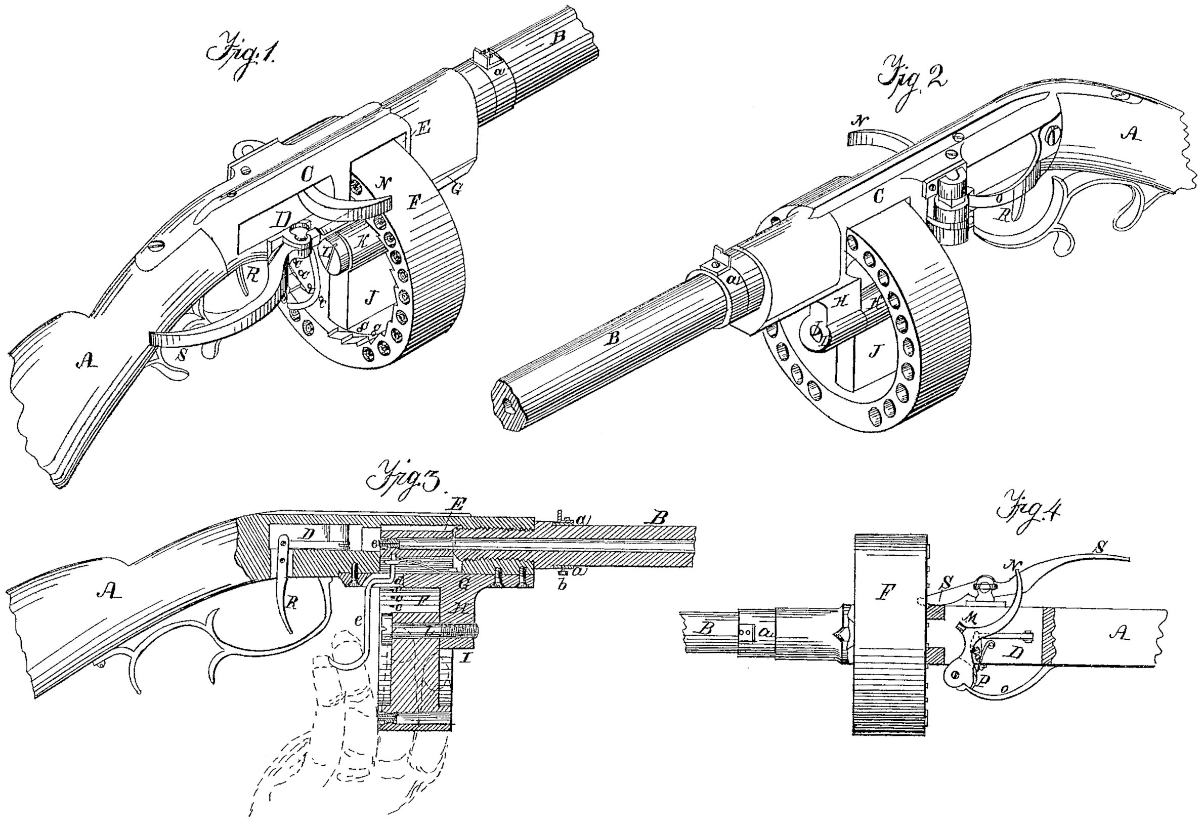
Figures 1 and 2 represent perspective views of that part of the fire-arm to which my improvement is applied, taken from different positions. Fig. 3 represents a vertical longitudinal section through so much of the arm as is shown in Fig. 1. Fig. 4 represents a top view.
Similar letters, where they occur in the several figures, denote like parts in all.
The nature of my invention relates to the ring of chambers, particularly its construction and operation.
To enable others skilled in the art to make and use my invention, I will proceed to describe its construction and operation in connection with the accompanying drawings.
A represents the stock, and B the barrel, of any common construction.
C is a metallic piece interposed between the stock and the barrel for the receipt of the lock and the ring of chambers and their several connections, which piece C may be termed the breech-frame or breech-piece. Through this breech-piece C are made two horizontal rectangular mortises, D E, the rear one, D, for containing the lock, as will be explained, and the front one, E, for the ring F, which contains the chambers to pass through.
Underneath the piece C is secured a plate, G, to the under side of which plate is cast or otherwise connected an arm, B, terminating in a hub, I. The ring F has a single spoke, J, terminating in a hub, K, at its center, and through these two hubs I K passes an axle bolt, L, so that said ring may turn on a fixed center.
The barrel B is screwed into the breech-piece C, and just projects into the front of the front mortise, E, as seen in Fig. 3, so that the depth of the ring F shall close up the mortise between the end of the barrel and the rear of the mortise.
The ring may be very closely fitted to the mortise in the direction of its depth without in any manner interfering with its freely turning, because the ring, in the first place, turns upon fixed center, which prevents it from getting skewed in the mortise, and the expansion of metal in firing the arm is about equal between the breech-piece and the ring, which prevents undue friction in that respect. The mortise in its vertical line may be much larger than the ring, so as to have a free circulation through it.
In the use of the arm of course that end of the barrel against which the ring turns will Wear or burn away to some extent. To remedy this the barrel may be screwed into the breech piece farther to close up any such wearing away; and then to adjust the sights again after turning the barrel I make and attach the sights to rings or collars a, which can be turned on the barrel, and when properly adjusted they may be held by set-screws b, Fig. 3.
Of the lock, M is the hammer, and N the thumb-piece for cocking it. O is the main spring, P the dog, and Q the sear. R is the trigger for releasing the hammer; f, the sear-spring.
I have shown in Figs. 1 and 4 a lever, S, for turning the ring F, the point of said lever taking into ratchet-teeth in the inner periphery of the ring. I do not, however, purpose to use this lever, as the arm operates better without it, and all superfluous pieces about a fire-arm are only injurious or detrimental to its use. In the inner periphery of the ring are a series of recesses, c, corresponding to the number of chambers in the ring, and on top of the plate G, which is the bottom of the mortise E, Fig. 3, is secured a spring, d, to which a bolt, e, is attached, so that the upper end of said bolt will take into the series of recesses c as the ring F is turned. The lower part of the bolt e is so formed as to hang down in convenient position for the user, so that he may readily release the ring to allow it to turn and as readily release the bolt to allow it to take into the next recess, and thus stop each successive chamber in the ring in line with the bore or barrel of the fire arm, where it may be discharged by releasing the hammer in the usual well-known manner.
The advantage of the ring over the cylinder or disk or wheel of chambers is this— that it can be made to contain more charges than the cylinder with much less weight of metal, and that the chambers all point forward instead of radial, as in the wheel or disk. As to the block breech—viz., that which reciprocates horizontally or vertically past the barrel or bore of the gun— they are impracticable, because to make them fit their mortise Snug enough to direct them in their movements they become so tight as to be immovable when the metal expands by heat in firing. With a ring having a fixed center to turn on and the facility of almost an entire revolution, as mine is arranged, and a back and front support to the ring at the point where the chambers are discharged, I have removed the serious objections heretofore encountered in this class of guns.
To fire this gun the user should place his supporting-hand under the ring, as seen in red dotted lines, Fig. 3, with the two forefingers around the ring F, and the third finger over the bent end of the spring-bolt e. The hammer having been first cocked, the bolt e is slightly drawn down by the finger, and the ring freely turns by mere motion of the wrist joint. The bolt almost as instantly as drawn down should be again let go, so as to catch into the first of the series of recesses that come around, and the moment the bolt catches the arm is ready to be fired, and so on until the twenty-five (more or less) chambers are discharged, when by the same position of the supporting-hand and third finger the cylinder can be turned back again to be recharged for another series of discharges.
Having thus fully described the nature of my invention, what I claim therein as new, and desire to secure by Letters Patent, is—
1. The ring of chambers, having a single spoke extending from its inner periphery to its hub, so that said ring may turn on a center support, make almost an entire revolution, and pass freely and truly through the mortise in the breech, where its chambers are in succession brought opposite or in line with the bore of the gun, substantially as described.
2. So combining the bolt e with the ring of chambers as that it may be detached from its catch and the ring turned to bring the next chamber in line by the hand which supports the gun and without changing the hand from its supporting position, substantially as set forth.
ALEX. HALL.
Witnesses:
A. B. Stoughton,
Thos, H, Upperman.