
US 14780
UNITED STATES PATENT OFFICE.
SIMON F. STANTON, OF MANCHESTER, NEW HAMPSHIRE.
IMPROVEMENT IN BREECH-LOADING FIRE-ARMS.
Specification forming part of Letters Patent No. 14,780, dated April 29, 1856,
To all whom it may concern:
Be it known that I, Simon French Stanton, of Manchester, in the county of Hills borough and State of New Hampshire, have invented certain new and useful Improvements in Breech-Loading Fire-Arms, of which the following is a full, clear, and exact description, reference being had to the annexed drawings, making part of this specification, in which—
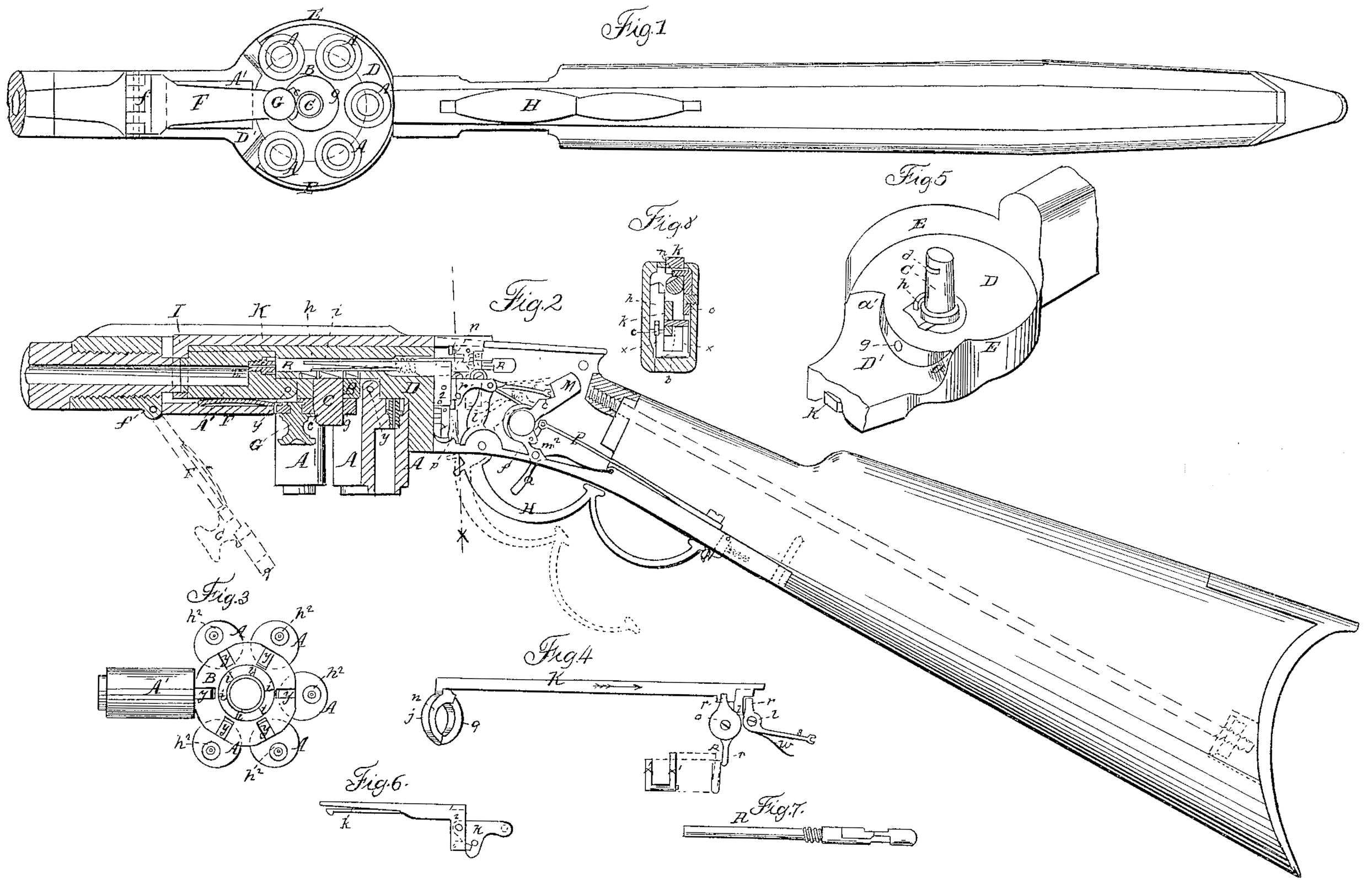
Figure 1 is a view of the gun, seen from beneath; Fig. 2, a longitudinal section through the same; Figs. 3, 4, 5, 6, and 7, details which will be referred to hereinafter; Fig. 8, a cross section upon the line XX of Fig. 2.
My improvements are upon that class of fire-arms in which the charge-chambers are pivoted to a revolving plate, from which they are allowed to hang down vertically, only one of them being brought up at a time in line with the barrel previous to the discharge.
In guns of this description as heretofore made, after the charge-chambers have been revolved they are elevated by a separate manipulation, a separate and independent device being employed for the purpose. In my improved gun the charge-chambers are raised to their position in line with the barrel by the act of revolving them, whereby separate devices for the purpose are rendered unnecessary, and the construction and manipulation of the gun is much simplified.
My invention also consists in certain improvements in the details of the lock, the nature of which will be more particularly pointed out hereinafter.
To enable others skilled in the art to understand my invention, I will proceed to explain the manner in which I have carried it out.
In the accompanying drawings, the charge chambers A A’ are hinged at y to the circular plate B, which revolves around the pin C, rising from the breech-piece D. (Seen in perspective in Fig. 5.) To facilitate the removal of the chambers from the gun, they are confined thereto in the following manner:
F is a lever, pivoted at f, and having a hole at its other extremity, g, through which the pin C passes, Figs. 1 and 2.
G is a button or catch, having a projecting lip, e, which enters a notch, d, in the pin C, by which means the lever F is secured in place and the charge-chambers are confined in position, as required.
On an examination of Fig. 5 it will be observed that at D’ the breech-piece is cut away. The portion D sustains and steadies the plate B, which is held up against it, while the portion D’ permits the chambers to be raised into line with the barrel, as will be hereinafter described. Between these there are two inclined planes, a a’, the object of which will be presently described.
E is a flange rising from the breech-piece around about three-fourths of its circumference, which serves to retain the chambers in their vertical position.
The charge-chambers are revolved as follows: The spring hook or pawl h is seen detached in Fig. 6, and is connected by means of the link k With the inner end, l, of the cocking lever H, which also serves the purpose of a guard. As this lever is thrown into the position seen in red in Fig.2 it retracts the spring-hook h, which, coming in contact with the teeth i upon the plate B, revolves this plate, and with it the charge-chambers, one-sixth of a revolution. As this takes place the inner extremity of one of the charge-chambers, being no longer sustained in its vertical position by the flange E of the breech-piece, strikes against one side of the lever F, and by it is gradually raised into position in line with the barrel, as seen at Ain Figs. 1, 2, and 3. When in this position a spring, m, holds it up against the breech-piece until the joint between the chambers and the barrel is covered. This is effected in the following manner:
I is a ring upon one end of the rod K, (seen detached in Fig. 4) having a notch at one extremity, into which enters a pin, n, projecting from a plate, o. Pivoted to the lock-case p is a finger upon the opposite side of the plate o, against which a pin, r, Figs. 8, 4, and 6, projecting from the link k, strikes as the lever H is returned to its place, by which means the rod K is moved in the direction of its arrows, Fig. 4, and the ring is drawn over the joint. In order to insure that this joint shall be covered before the gun can be discharged, the following device is employed.
s is a safety-stop pivoted to the lock-case at t, and having, a pin, v, projecting therefrom, against which the lever K strikes when it is drawn back, by which means the stop s is depressed, as seen in Fig.2, and is thereby cleared of the hammer M, which is then not intercepted in its fall. When, however, the lever H is not returned entirely to its position and secured beneath its spring-catch N, and the ring I is consequently not drawn over the barrel and charge-chamber, the stop s is thrown by the spring w into the position seen in red in Fig. 2, and if the hammer be then let off its fall is arrested by the stop and the piece is not discharged.
The ring I is drawn from off the joint, between the barrel and chamber in the following manner: Beneath the link k and lever h, Fig. 8, is a lever having two arms or branches, x’ x^2, the former of which has a notch, into which catches a pawl, c’, hinged to the carrier z of the spring-hook h, and forced down by a spring. (Not seen in the drawings.) As now the lever H is thrown down and the spring-hook is drawn back the pawl c’ engages with the arm x’ of the lever and carries the other arm, x^2, against the finger p, and thus the rod K is moved in a direction contrary to its arrow, Fig. 4, and the ring I is drawn off the joint before the spring-hook engages with the teeth i to revolve the charge-chambers. In order that the ring I may arrest the motion of the chambers at the instant of their arrival in line with the barrel, it is cut, away upon side, as seen at q, Fig. 4, and drawn back slightly before the arrival of the chamber, so that the latter is arrested by striking against the thick portion r of the ring. This backward motion of the ring is effected as follows: A shoulder, 1, upon the carrier z (seen dotted in Figs. 2 and 6) strikes against the dog 2 projecting from the bar K, and moves this bar backward one-sixteenth of an inch, or thereabout, and the chamber, although allowed to pass the thin portion g of the ring, is arrested by the thicker portion r, as before mentioned, and prevented from being carried past the barrel by its momentum.
The piece is cocked and discharged in the following manner: As the lever H is depressed the extremities of its short arm l presses against the hammer M and forces it back against the action of the spring P until the trigger Q falls into its notch in the tumbler f^2. When the trigger is pulled the hammer flies against the hammer-rod R., (seen detached in Fig. 7) by which the latter is thrown through the hole g^2, Fig. 5, against the cap upon the nipple h^2, and the piece is discharged. When the gun is not cocked the trigger lies concealed within a recess in the lock-plate, into which it is thrown by the spring m^2.
What I claim as my invention, and desire to secure by Letters Patent, is—
1. Raising the chambers into line with the barrel by the action of revolving them, in the manner substantially as herein set forth.
2. The peculiar form of the breech-piece, with its elevated and depressed portions D D’, and inclined planes a. a’, whereby as one charge chamber is raised into line with the barrel the one last discharged is forced down by the inclined plane a’ into its vertical position, as set forth.
3. The method herein described of securing the chambers in position without interrupting their motions by means of the lever F, operating in the manner substantially as herein set forth.
4. The ring t, constructed and operating in the manner substantially as herein set forth, for the purpose of arresting the motion of the revolving chambers and closing the joint be tween the barrel and the chamber, as described.
5. The combination of devices or their equivalents whereby the ring I is driven forward to release the charge-chambers before they are revolved, as set forth.
6. The safety-stop, operating in the manner substantially as herein described, for the purpose of preventing the fall of the hammer whenever the ring I is not drawn over the joint between the barrel and the charge-chamber.
S. F. STANTON.
Witnesses:
Jos. L. Cilley,
B. P. Cilley.