
US 14406
UNITED STATES PATENT OFFICE.
F. NEWBURY, OF ALBANY, NEW YORK.
IMPROVEMENT IN REVOLVING FIRE-ARMS.
Specification forming part of Letters Patent No. 14,406, dated March 11, 1856.
To all whom it may concern:
Be it known that I, Frederick Newbury, of the city of Albany and State of New York, have invented certain Improvements in the Construction of Fire-Arms; and I declare the following specification, with the drawings hereto attached as part thereof, to be a full and perfect description of the same.
My invention is for the application to fire arms of a magazine for a number of charges and a magazine for percussion-priming caps, with their operating apparatus.
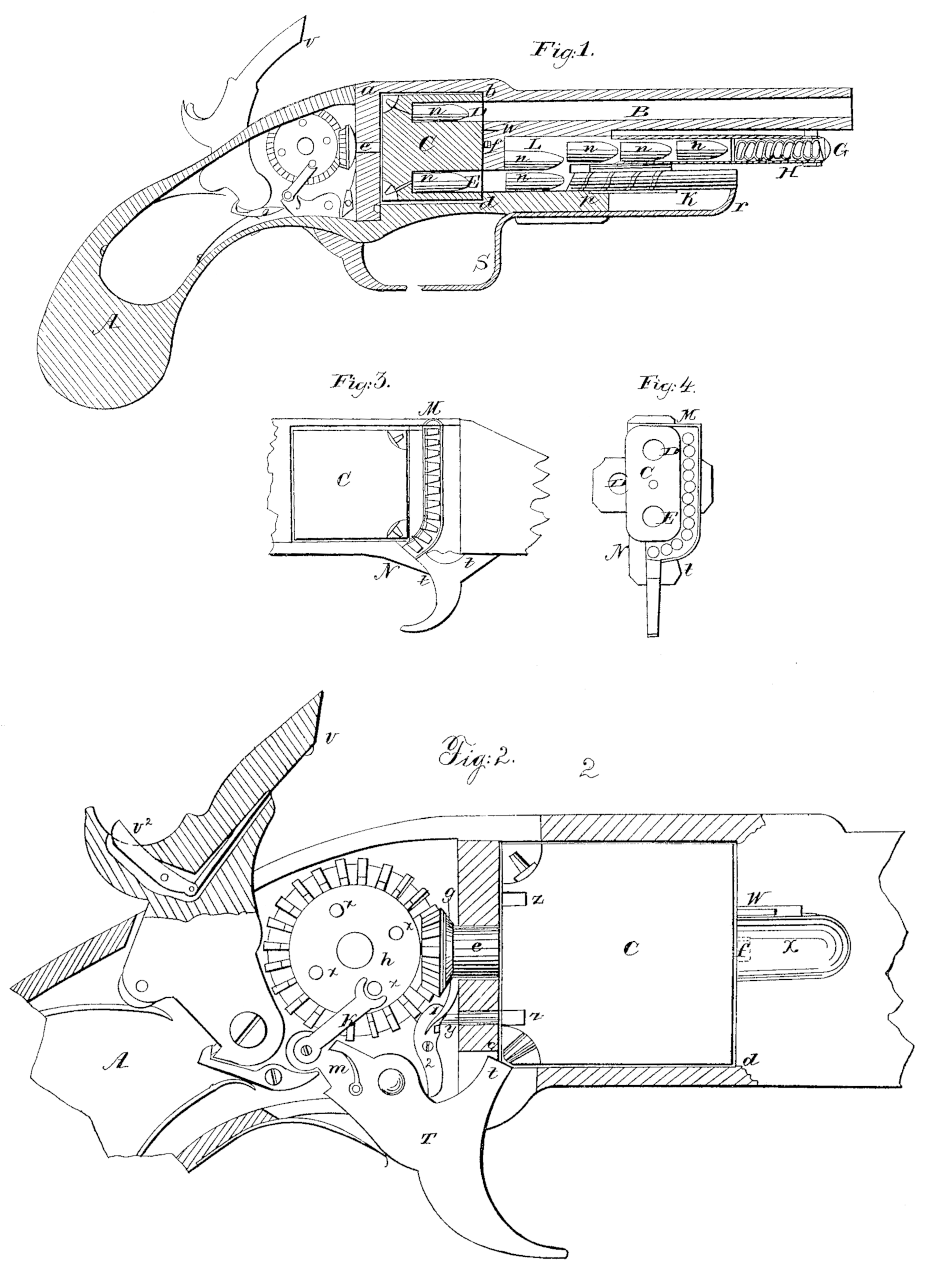
Figure 1 represents a longitudinal section of a pistol, to show the internal arrangement and operation of the apparatus; Fig. 2, the operating apparatus on a large scale, also in longitudinal section; Fig. 3, a profile view of a portion of the breech with the priming-cap chamber attached, which is shown in profile section, Fig. 4, which is a cross-section of the revolving load-chamber, and the priming-cap chamber also.
Similar letters in the different figures denote the same parts of the apparatus.
The stock A is connected with the barrel B with usual metal frame – work, similar to the arrangement of the Colt’s revolver, having a square or oblong opening, at b c d, between the stock and barrel, within which, in Colt’s piece, his load-chamber revolves. Within this opening revolves an oblong block of metal, C, turning on pivots e f. It has two chambers, D E, equidistant from the center, and coinciding with the barrel B as the block revolves. The chambers, moreover, are slightly larger than the barrel, in order to slug the ball. Each chamber has in its rear outer angle a cone for priming-cap countersunk in it, as shown in the drawing. This block is revolved by the following apparatus: To the pivot e is attached a bevel pinion-wheel, g, cogging into a bevel spur-wheel, l. The spur-wheel is most conveniently made to give two revolutions of the pinion to one of its own. Projecting from its face are four pins, a x x x x. The trigger T has pivoted to its projecting back limb a pawl, k, whose upper end presses against the pins a, so as to revolve the wheel h a quarter-circle with every pull of the trigger. The pawl is kept in its place by the spring m.
It will be seen that by this arrangement every pull of the trigger will turn the block C a half-revolution, bringing alternately each chamber D and E in range with the barrel.
To maintain the chambers and barrel in range during the firings, a stop plug or bolt, y, Fig. 2, passing through the face-plate back of the revolving block, can center into sockets z, made in the block, and is kept in place by a spring, 1. The bolt y is attached to a lever, 2, pivoted near its center, and whose lower end lies in a notch of the trigger, so arranged that while the trigger lies forward the bolt is withdrawn from the socket, but when drawn back for firing the bolt can shoot forward, pressing against the face of the block C until the socket reaches it, when it falls in and keeps the block firm until the discharge takes place, after which the return of the trigger to first position with draws the bolt and leaves the block free to turn.
The magazine for charges is a movable tube of thin metal, G, lying just under the barrel, its inner end opening into a chamber in the metal frame-work lying in front of the block C. Into this tube the cartridges n n are placed by removing the tube and entering them from the inner end. As they are inserted they compress a spiral spring, H, coiled in the tube, and resting against the outward and closed end thereof, the spring having power enough to force back the cartridges to the inner end of the tube as each in succession passes out.
The chamber L is of sufficient size to receive two cartridges, one lying above the other. The lower part of chamber L. ranges with the chambers D and E in the block as they come round in succession.
From the lower part of chamber L projects a shut tube, K, lying under and parallel with G. It contains a ramrod, p, which is kept habitually beyond the chamber L by a spring. From its outer end a bent rod, r, passes downward and back, and is attached to the front limb of the trigger-guard S. By pressing back the guard S with a finger the cartridge lying in L will be transferred to the chamber D or E, and when the pressure is withdrawn the ramrod will be carried back by the spring, and the empty chamber L immediately occupied by the cartridge lying above it in the tube G. The vacancy in the tube G will be supplied by an other cartridge pressed back by the spring H.
The magazine for priming-caps is shown at MM, Fig. 3 and 4. It is a chamber lying behind the revolving block on the side of the stock, either at right angles to the axis of the block or sloping, so that when the weapon is aimed horizontally the caps may roll downward; or a spring may be used to force them. The lower end of the chamber curves under the stock, so as to deliver the lowest cap opposite to and in range with the cone on the lowest angle of the revolving block. This also brings the cone in range with a limb, t, of the trigger, by whose upward motion the priming-cap is pressed home on the cone. The cap being in place, the withdrawal of t leaves room for a succeeding cap to fall into the vacancy between the trigger and block.
The connection between the movement of the trigger and the operation of the hammer will be understood from the drawings, and needs no description.
On the lower striking-edge of the hammer, at V, a small piece of steel is made to project forward, whose office it is, after the caps have been exploded, to pick them off the cone as the hammer is raised by the act of cocking piece. It is operated by a thumb-piece lever, V^2, inserted into the hammer and attached to it by a stem, so that on pressing upon the piece in cocking, the hammer V will be thrown forward under the burst caps and lift them off the cone.
I note here that the reason why I revolve the block C by the trigger, and not by the hammer, as is done in other revolvers, is because it is necessary that the block C should remain stationary until the process of raising the hammer has thrown off the exploded cap.
To prevent the possibility of the fire of explosion extending from the upper to the lower chamber, I insert in the framing a sliding guard-plate, W, being a flat piece of metal fitting tightly against the block C, and kept in place by a spring lying in a 1’ecess behind it.
Whenever it may be desirable, for want of proper cartridges, to load with loose powder and ball, this can be done by turning the revolving block across the stock, as shown in Fig. 4. In order to uncover that portion of the charge-chamber which will be opposite to the frame-work in front of it, a recess sloping down to the mouth of the chamber is sunk in the frame-work, as shown by the shading at X in Fig. 2.
The operation of loading and firing is as follows: The chambers D and E can be loaded with cartridges by turning the block across the frame, as shown in Fig. 4, a priming-cap to be placed upon the cone of the chamber that will be undermost at the first pulling of the trigger, and then the chamber is to be turned to the proper position for firing. Then, the tube G being withdrawn, two cartridges can be inserted into the chamber L. The tube G is then to be filled with cartridges and put in its place, when the condition of the whole will be as shown in Fig. 1. The priming-chamber M N is to be filled with caps, which will bring the lowest cap upon or against the trigger. The piece is now to be cocked. Then, the trigger being drawn, the pawl k, pressing upon the pin x, turns the spur-wheel h, pinion g, and by them the block C, until it has made a half-revolution and chamber E has ranged with the barrel. In the meantime the stop-pin y, having been released by the withdrawal of the trigger, presses against the back surface of the block by its spring, and at the instant the chamber and barrel align with each other it drops into the notch & and holds the block steady. At the same instant the hammer is tripped, and drops down on the cap, firing the piece.
The trigger, when released, is thrown for ward by its spring, withdrawing the bolt y from its socket z, and pressing to its place a priming-cap, which, when the trigger was back, had dropped into the space between the trigger and cone, as shown in Figs. 3 and 4.
Upon the second firing the same operations occur, and then an empty chamber is brought down in range with the loading apparatus. Now, before firing, the guard S is to be drawn back by the finger, by which a cartridge is pressed into the chamber, which, on the withdrawal of the ramrod K, is supplied from above, and the firing goes on as above described, first loading by means of the guard S.
Some of the peculiar excellencies of the invention I conceive to be these: First, its small size and light weight for the number of charges it is capable of carrying; second, its safety from accidental firing, because an accidental rise and fall of the hammer can effect nothing, since the upper chamber is not loaded and capped unless it be brought up from below by the movement of the trigger; third, its safety from bursting, if by any chance fire should be communicated to the magazine, for the load tube and the ramrod-tube are so light that they would be blown away without endangering the person holding the weapon; fourth, the strong security against fire communicating from the explosion in the barrel effected by the spring-guard plate; fifth, the ease with which the weapon can be loaded and fired in succession with one hand, the loading-guard S, the hammer, and trigger being all within the reach of the thumb and forefinger.
What I claim, and desire to secure by Letters Patent, is the following apparatus, substantially as set forth in the above specification, viz:
1. The combination of wheel-gearing and pawl with the trigger, by which means the block C is revolved; the wheel-gearing itself not claimed.
2. The priming-cap magazine, in combination with the trigger, to permit the capping the cone by the trigger.
3. The spring-guard plate, to prevent the fire from the upper chamber extending to the lower.
4. The combination of the picker attached to the hammer with the apparatus operated by the thumb in the act of cocking the hammer, substantially as set forth in the above specification.
E. NEWBURY.
Witnesses:
Richd. Vareck De Witt,
W. C. MILLER.