
Britain 3154
A.D. 1870, 1st December. № 3154
Revolving Fire-arms.
LETTERS PATENT to Alexander Melville Clark, of 53, Chancery Lane, in the County of Middlesex, Patent Agent, for the Invention of “Improvements in Revolving Fire-arms.”-A communication from abroad by Charles John Linberg and William John Phillips, both of the City and County of St. Louis, State of Missouri, United States of America.
Sealed the 25th April 1871, and dated the 1st December 1870.
PROVISIONAL SPECIFICATION left by the said Alexander Melville Clark at the Office of the Commissioners of Patents, with his Petition, on the 1st December 1870.
I, Alexander Melville Clark, of 53, Chancery Lane, in the County of Middlesex, Patent Agent, do hereby declare the nature of the said Invention for “Improvements in Revolving Fire-arms,” to be as follows:
This Invention relates to improvements in revolving pistols or other fire-arms, and it consists in mounting the barrel on an axis parallel with the axis of the cylinder in such a manner that the securing of the barrel with the cylinder for firing and the releasing of the cylinder for loading is effected by swinging it sidewise in a manner better calculated for convenience in manipulating the arm than the present arrangements.
The Invention also comprises an arrangement of two cylinders to be shifted on the spindle for being respectively used, said cylinders being provided with needles contained in one of the spaces between the chambers, and communicating the blow of the hammer through the rearmost to the caps on or the cartridges in the one to be fired placed at the front. The said cylinders are also arranged so that the caps or cartridges are protected from wet and accidents by cavities and bases, which meet together and form completely enclosed chambers when placed on the spindle with the ends having the caps placed together.
The Invention also comprises an improved arrangement of operating gear for revolving the cylinders, comprising a push bar communicating motion from the hammer through a channel under and at one side of the cylinders to a bell crank and lifting pawl in a chamber at the rear and below the barrel, which pawl acts on a ratchet on the end of the front cylinder, and is retracted by a spring. The cylinders, of which there are two, are mounted on a common spindle, the barrel being mounted on a pivot pin projecting from the end of the stock below the chambers and parallel with their spindle, said pin passing through an arm projecting from the stock of the barrel. This stock carries a shoulder piece which swings into a cavity in the upper side of the spindle, and firmly locks the barrel against the tendency of the force of the discharge to throw it forward. The barrel is held in position against swinging back by a plate pivoted to the stock of the barrel, and swinging at the free end up past ratchet teeth which project slightly from the end of the front cylinder, or it may bear against the side of the cylinder spindle. One cylinder has an annular recess at the end having the nipples for receiving the caps, and the other has a corresponding projecting flange fitting the said recess, and shutting in the chamber in which the nipples and caps are contained, said chamber being formed by annular grooves in the ends of the said cylinders. Each cylinder is provided in a longitudinal hole formed between two of the chambers, with a needle or rod capable of a slight movement lengthwise, and arranged for receiving the blow of the hammer and communicating it to the cap in front of it to be exploded. The rear cylinder is held so as not to revolve, and for its needle to receive the hammer at the rear end by a pin projecting from the seat of the stock for the rear ends of the cylinders into a hole suitably arranged in the end of each cylinder for it, and the front cylinder is held by a locking lever, so that the caps for the respective chambers will be in front of the needle. The rotation of the front cylinder is effected by a pawl jointed to a T headed lever acted on by a sliding push bar. The latter extends backward under one side of the cylinders in a groove in the stock to the hammer arm, to the side of which below its pivot it is connected by a stud pin which passes through an oblique slot in the said bar, and imparts a forward movement to it when the hammer is raised, throwing the front end which is bevelled under the one arm of the T headed pawl lever, which being pivoted at the other arm will force up the pawl and turn the cylinder. The falling of the hammer draws the sliding bar back, and the pawl is thrown back by a spring. The theaded pawl lever and the spring are arranged in a cavity in the barrel stock at the side opposite to that on which is the plate before referred to, which cavity is covered by a thin plate capable of being readily detached when access is desired. The sliding bar and the pawl lever are so arranged that when the hammer is on “half cock” the point of contact between them coincides with the line of the joint between the barrel stock and the cylinder stock, so that when in this condition the barrel may be swung around to detach the cylinder. The cylinder locking lever before mentioned is thrown down at the moment the pawl begins to act on the ratchet by the head of a spring on the sliding bar passing under a projection on the lower end of the locking lever. This lever is thrown up again as soon as the head of the spring passes beyond the projection by another spring, and the upper end is forced into the notch in the cylinder when the said notch arrives at the right position. When the sliding bar moves back the head of the spring passes at the side of the projection on the locking lever, the latter being suitably bevelled on one side to allow the former to go back without catching. By the employment of the two cylinders, which are shifted when one has been exhausted, the empty one being placed at the rear and the other at the front, the capacity of the arm is doubled, and it may be further increased by the employment of any number of extra cylinders, all fitted alike to apply loaded ones as the others are discharged, the said extra cylinders being carried in holsters suitably adapted for the purpose, or in any other convenient way. By the employment of two cylinders a better distribution of the weight of the arm is secured, for the weight being more distant from the hand the latter is more sensitive to its influence in bringing it to the eye and holding it there than when the weight is nearer the hand. The arrangement of the two cylinders at the ends which meet together ensures protection to the caps from wet or accidents. I propose to screw the nipples into the rear ends of the cylinders, so that they may be readily detached for shooting cartridges instead of loose ammunition as may be preferred.
SPECIFICATION in pursuance of the conditions of the Letters Patent, filed by the said Alexander Melville Clark in the Great Seal Patent Office on the 25th May 1871.
TO ALL TO WHOM THESE PRESENTS SHALL COME, I, Alexander Melville Clark, of 53, Chancery Lane, in the County of Middlesex, Patent Agent, send greeting.
WHEREAS Her most Excellent Majesty Queen Victoria, by Her Letters Patent, bearing date the First day of December, in the year of our Lord One thousand eight hundred and seventy, in the thirty-fourth year of Her reign, did, for Herself, Her heirs and successors, give and grant unto me, the said Alexander Melville Clark, Her special licence that I, the said Alexander Melville Clark, my executors, administrators, and assigns, or such others as I, the said Alexander Melville Clark, my executors, administrators, and assigns, should at any time agree with and no others, from time to time and at all times thereafter during the term therein expressed, should and lawfully might make, use, exercise, and vend, within the United Kingdom of Great Britain and Ireland, the Channel Islands, and Isle of Man, an Invention for “Improvements in Revolving Fire-arms,” a communication to me from abroad by Charles John Linberg and William John Phillips, both of the City and County of St. Louis, State of Missouri, United States of America, upon the condition (amongst others) that I, the said Alexander Melville Clark, my executors or administrators, by an instrument in writing under my, or their, or one of their hands and seals, should particularly describe and ascertain the nature of the said Invention, and in what manner the same was to be performed, and cause the same to be filed in the Great Seal Patent Office within six calendar months next and immediately after the date of the said Letters Patent.
NOW KNOW YE, that I, the said Alexander Melville Clark, do hereby declare the nature of the said Invention, and in what manner the same is to be performed, to be particularly described and ascertained in and by the following statement, reference being had to the Sheet of Drawings hereunto annexed, and to the letters and figures marked thereon (that is to say):—
This Invention relates to improvements in revolving pistols or other fire-arms, and it consists in mounting the barrel on an axis parallel with the axis of the cylinder in such a manner that the securing of the barrel with the cylinder for firing and the releasing of the cylinder for loading is effected by swinging it sidewise in a manner better calculated for convenience in manipulating the arm than the present arrangements.
The Invention also comprises an arrangement of two cylinders to be shifted on the spindle for being respectively used, said cylinders being provided with needles contained in one of the spaces between the chambers and communicating the blow of the hammer through the rearmost to the caps on or the cartridges in the one to be fired placed at the front. The said cylinders are also arranged so that the caps or cartridges are protected from wet and accidents by cavities in bases, which meet together and form completely enclosed chambers when placed on the spindle with the ends having the caps placed together.
The Invention also comprises an improved arrangement of operating gear for revolving the cylinders, comprising a push bar communicating motion from the hammer through a channel under and at one side of the cylinders to a bell crank and lifting pawl in a chamber at the rear and below the barrel, which pawl acts on a ratchet formed on the end of each cylinder, and is retracted by a spring.
DESCRIPTION OF DRAWINGS.
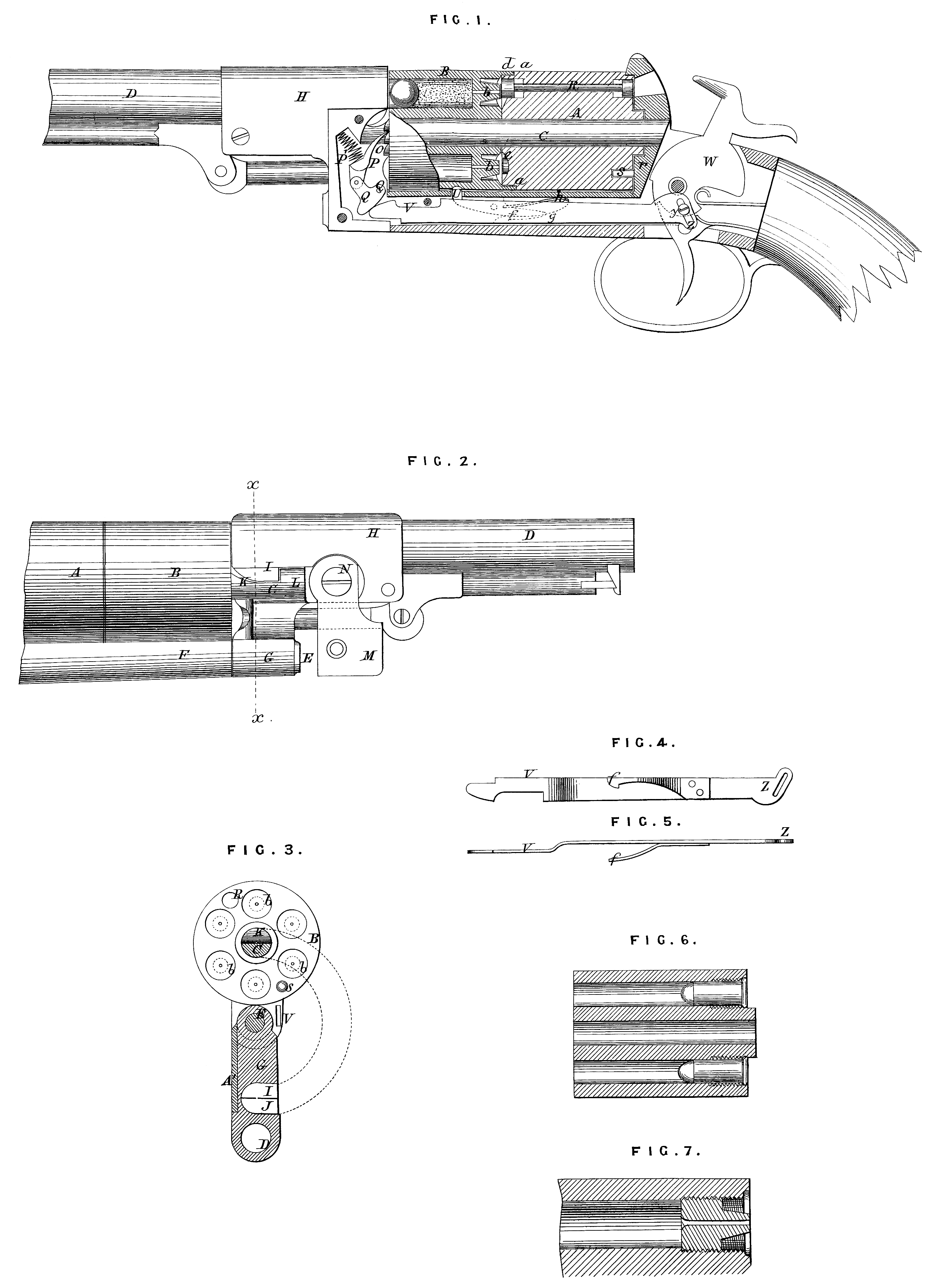
Figure 1 is a longitudinal sectional elevation of the improved revolving fire-arm; Figure 2 is a side elevation of the same; Figure 3 is a trans verse section taken on the line x, x, of Figure 2; Figure 4 is a side view of the sliding bar and spring used for actuating the revolving cylinders; Figure 5 is an edge view of the same; Figures 6 and 7 are sectional views of the cylinders showing the detachable nipples. Similar letters of reference indicate corresponding parts.
A and B represent the cylinders, and C the spindle on which they are mounted; D represents the barrel; it is mounted on the pivot pin E projecting from the end of the stock F below the chambers and parallel with the spindle C, said pin E passing through the strong arm G projecting from the stock H of the barrel. This stock, which has a hollow cavity J at the under side, carries the shoulder piece I, which swings into the cavity K in the upper side of the spindle C behind the shoulder L, and firmly locks the barrel against the tendency of the force of the discharge to throw it forward, and the bottom of the cavity J arrests the barrel when closing. The barrel is held in position against swinging back by the plate M pivoted to the stock Hat N, and swinging at the free end up past the ratchet teeth O, which project slightly from the end of the cylinder, or it may bear against the side of the spindle C. One cylinder has an annular recess a at the end, having the nipples b for receiving the caps, and the other has a corresponding projecting flange d fitting the said recess and shutting in the chamber e in which the nipples and caps are contained, said chamber being formed by annular grooves in the ends of the said cylinders. Each cylinder is provided (in a longitudinal hole formed between two chambers) with a needle or rod R capable of a slight movement lengthwise, and arranged for receiving the blow of the hammer and communicating it to the cap in front of it to be exploded. The rear cylinder is held so as not to revolve and for its needle to receive the hammer at the rear end by a pin S projecting from the seat T of the stock into a hole suitably arranged in the rear end of the cylinder for it, and the front cylinder is held so that the caps for the respective chambers will be in front of the needle by the locking lever U. The rotation of the front cylinder is effected by the pawl P, T headed lever Q, and sliding push bar V, the latter extending backward under one side of the cylinder in a groove in the stock F to the hammer arm W, to the side of which, below its pivot, it is connected by the stud pin y, which passes through the oblique slot Z in the said bar, and imparts a forward movement to it when the hammer is raised, throwing the front end, which is bevelled, under the one arm of the T headed lever Q, which being pivoted at the other arm, as shown at Q¹, will force up the pawl P and turn the cylinder. The falling of the hammer draws the bar V back, and the spring P¹ throws the pawl P back. The pawl lever Q and the spring are arranged in a cavity in the arm G of the stock H at the side opposite to that on which plate M is, which cavity is covered by a thin plate A¹, which may be readily detached when access is desired. The bar V and the lever Q are so arranged that when the hammer is on “half-cock” the point of contact between them coincides with the line of the joint between the barrel stock H and the cylinder stock F, so that when in this condition the barrel may be swung around to detach the cylinders. The cylinder locking lever U is thrown down at the moment the pawl P begins to act on the ratchet by the head of the spring f on bar V passing under the projection g on the lower end of lever U. This lever is thrown up again as soon as the head of spring f passes beyond projection g by spring h, and the upper end is forced into the notch in the cylinder when the said notch arrives at the right position. When the bar V moves back the head of the spring f passes head g at the side, the latter being suitably bevelled on one side to allow the former to go back without catching. By the employment of the two cylinders, which are shifted when one has been exhausted, the empty one being placed at the rear and the other at the front, the capacity of the arm is doubled, and it may be further increased by the employment of any number of extra cylinders, all fitted alike and applied ready loaded as the others are discharged, the said extra cylinders being carried in holsters suitably adapted for the purpose, or in any other convenient way. By the employment of two cylinders a better distribution of the weight of the arm is secured, for the weight being more distant from the hand, the latter is more sensitive to its influence in bringing it to the eye and holding it there than when the weight is nearer the hand. The arrangement of the two cylinders at the ends which meet together ensure protection to the caps from wet or accidents.
I propose to apply the nipples to the cylinders by screwing them in so that they may be readily detached for shooting cartridges or loose ammunition, as may be preferred. This is fully represented in Figures 6 and 7.
Having described the nature of the Invention, and the manner of performing the same, I declare that what I claim as the Invention to be protected by the herein-before in part recited Letters Patent is,—
1st. The barrel stock pivoted on an axis parallel with the axis of the cylinder for opening to disengage the cylinders, and having the cavity in the side for receiving the spindle C when closing with the cylinders, all substantially as specified.
2ndly. The locking plate M arranged with the barrel stock H and the projecting ratchet teeth O, substantially as specified.
3rdly. The two cylinders arranged in connection for alternate use and provided with the enclosed needles R arranged and operating substantially as specified.
4thly. The arrangement of the cylinders A, B, for enclosing the chamber containing the nipples and caps at the ends fitting together, substantially as specified.
5thly. The turning pawl P, lever Q, bar V, and hammer arm, all combined and operating substantially as specified.
6thly. The combination with the locking lever U having the bevelled head and slide bar V of the headed spring f, all substantially as 10 specified.
7thly. The nipples for the caps applied to the cylinders detachably for removing them to employ cartridges, substantially as specified.
In witness whereof, I, the said Alexander Melville Clark, have hereunto set my hand and seal, this Eighteenth day of May, in the year of our Lord One thousand eight hundred and seventy one.
A. M. CLARK. (L.S.)
Witness,
Jas. O. Dewey,
53, Chancery Lane,
London.