
US 12328
UNITED STATES PATENT OFFICE
A. O. H. P. SCHORN, OF MURFREESBOROUGH, TENNESSEE.
IMPROVEMENT IN PORTABLE FIRE-ARMS.
Specification forming part of Letters Patent No. 12,328, dated January 30, 1855.
To all whom it may concern:
Be it known that I, ALEXANDER O. H. P. SCHORN, of Murfreesborough, in the county of Rutherford and State of Tennessee, have invented a new and useful Improvement in Portable Fire-Arms; and I do hereby declare that the following is a full, clear, and exact description of the construction and operation of the same, reference being had to the annexed drawings, forming part of this specification, in which —
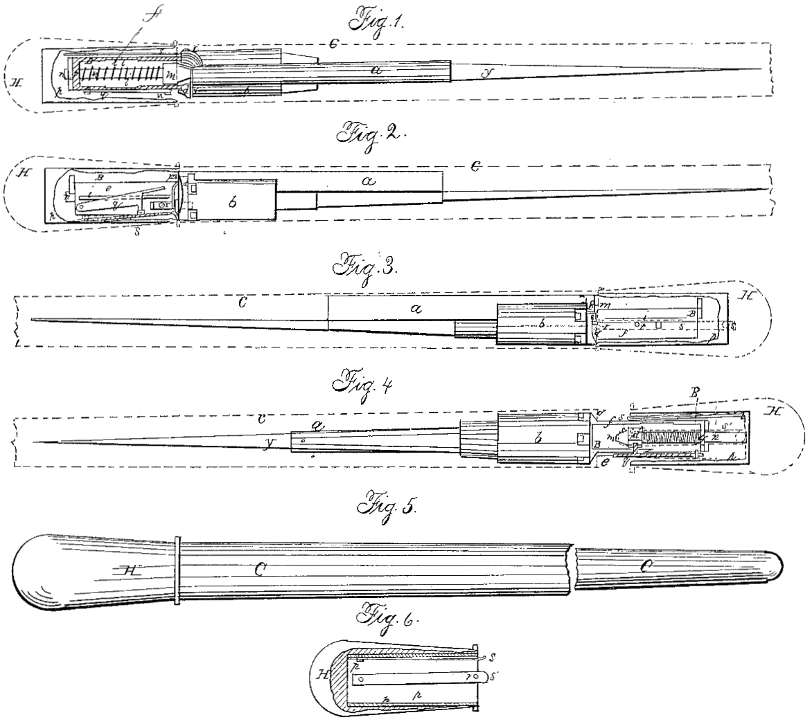
Figure 1 is a top view of the my improved fire-arm, with casing removed to show interior. Fig. 2 is a side view of the same, showing trigger. Fig. 3 is a view of opposite side, showing spring s. Gif 4 is a bottom view of same in position for firing. Fig. 5 is a view of case to which my improved fire-arm is adapted. Fig. 6 is a section of handle, showing springs s and s’ in position.
Similar characters of reference in the several figures denote the same part.
The object of my invention as an improvement in portable fire-arms is so to combine the mechanism of the fire-arm with the receptacle containing it that, while the weapon when not in use may be portable and completely protected from injury, the act of unmasking its concealed portions and bringing the fire-arm into an effective condition shall prepare it for the discharge. The manner in which I have accomplished this will be readily understood from the following description by reference to the drawings.
The invention is applicable to fire-arms of one or many chambers.
a is the barrel, and b a cylinder containing the charge-chambers, rotated by hand, as the invention is independent of any particular method of rotating the chamber. Behind the cylinder b, and fastened to the barrel a by a screw, c, is the head d, to which the discharging portion of the mechanism is attached. From this head there runs backward two plates of cheeks, e and f, each containing a longitudinal slot, i, Figs. 2 and 3, the two cheeks being connected in rear, as seen at g, thus forming a box, B, behind the cylinder, attached to the barrel by screw c. This box is traversed by a hammer, m, held in position by trunnions which run in the slots i, and forced forward by the coiled spring l, between the said hammer and the seat g, and wound around the bar n, which is fastened to the hammer and passed through an opening in the seat g, when the hammer is drawn back and the spring l compressed. This forms the portion of my invention connected with the barrel, and is rendered effective by combination with the following casing and parts connected therewith. The cylinder p is sufficient capacity to admit the above-described box. In it are the springs s and s’, as shown in Fig. 6. These springs have perforations r and r’, the former for the reception of the stud t on the under face of the hammer m, and the latter for the stud t’ on the cheek f, under the circumstances to be described. On the outside of the cheek e is a lever, q, having an arm, u, which as shown in Figs. 2 and 4, is directly above the spring s’. There is a small sliding guard, x, to hold the cylinder b and prevent its rotation when its movement is not desired. It does not, however, require a particular description. Under the barrel a is a small stiletto, y, not, however, essential to the construction of the weapon. The cylinder p is inserted in any suitable handle which will fit with a close joint over the covering of the barrel and cylinder. In the drawings the head H of a cane, C, is represented, though I do not design to restrict the covering of my improved fire-arm to that class of articles, as for military purposes a small belt-scabbard closing fitting a handle of any desired external form will combine portability with security to the mechanism of the weapon.
The following is the operation of the weapon: When the box B is within the cylinder p, the stud t of the hammer m enters the opening r in spring s’ so that as the box B is drawn from the receptacle the cheeks e and f move forward, and leave the hammer held by said spring s’, the stud t’ entering the opening r’ in spring s’, the stud t’ entering the opening r’ in spring s when the box moves sufficiently far forward, and resisting the spring l. A pressure on lever q depressed the spring s’, releasing the hammer m, which flies forward and discharges the load. By lifting spring s from stud t’, the box B is moved back, the stud t engages spring s’, and if the load be ready the arm is prepared for a new discharge.
By suitable and well-known devices the cylinder may be rotated by the backward movement of the casing p.
What I claim as new and of my own invention is —
The combination of the box B, springs s and s’, coiled spring l, hammer m, and casing p, constructed arranged, and operating as hereinbefore set forth, when used in connection with an external case, C H, for the purposes specified.
In testimony whereof I have hereunto signed my name before two subscribing witnesses.
A. O. H. P. SCHORN.
Witnesses:
GEO. PATTEN,
SAML. GRUBB.