
US 12471
UNITED STATES PATENT OFFICE
RALPH S. MERSHON AND JEHU HOLLINGSWORTH, OF ZANESVILLE, OHIO.
IMPROVEMENT IN REPEATING FIRE-ARMS.
Specification forming part of Letters Patent No. 12,471, dated February 27, 1855.
To all whom it may concern:
Be it known that we, RALPH S. MERSHON and JEHU HOLLINGSWORTH, of the city of Zanesville, county of Muskingum, State of Ohio, have jointly invented a new and useful Breech-Revolving Fire-Arm; and we do hereby declare that the following is a full, clear, and exact description of the construction and operation of the same, reference being had to the annexed drawings, making part of this specification.
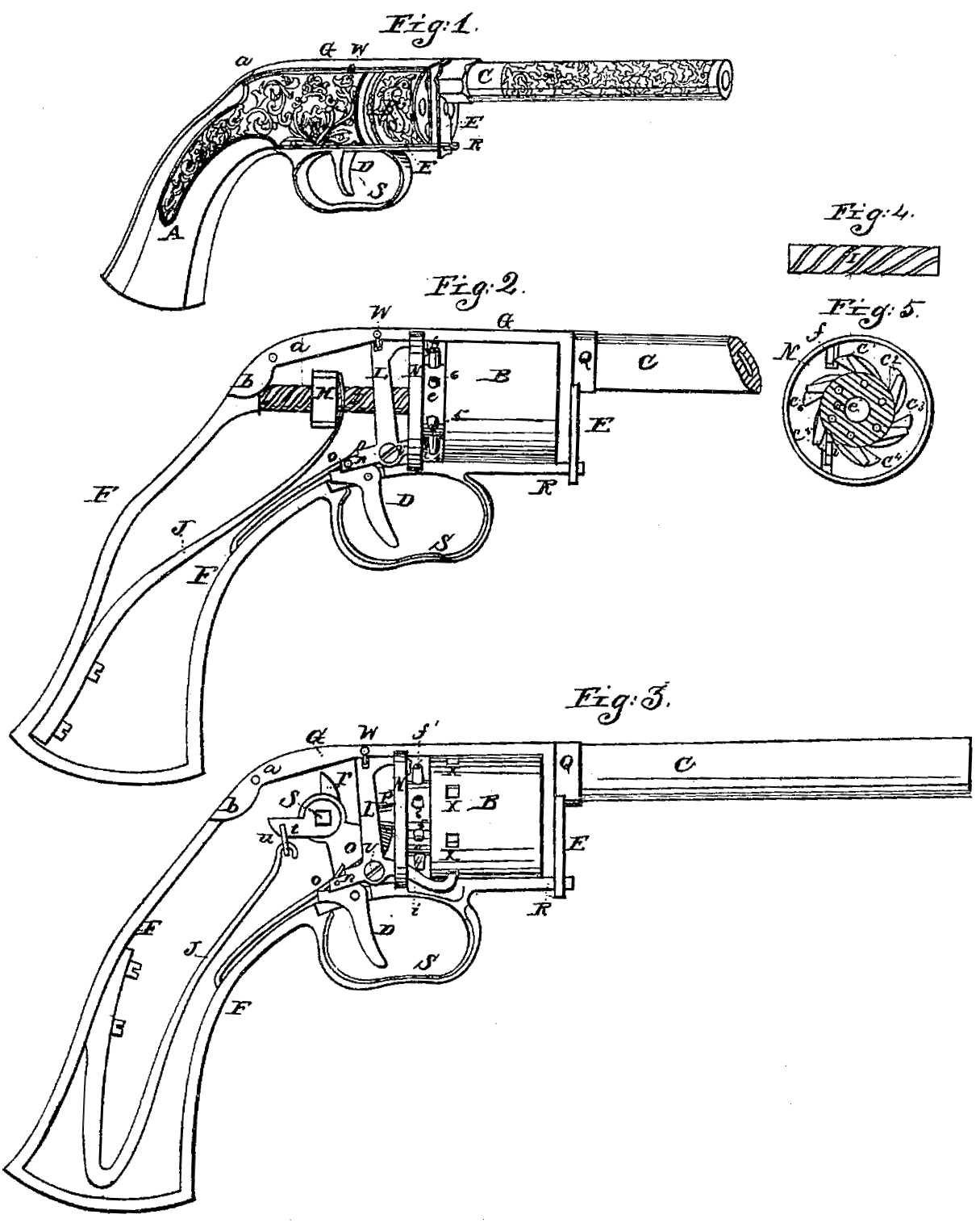
Figure 1 represents a perspective view of a pistol complete. Fig. 2 represents a side view of a pistol on an enlarged scale, with the cheeks of the stock removed to represent the internal parts more fully. Fig. 3 represents a similar view of a modified form of pistol involving the same general principle of that of Fig. 2. Figs. 4 and 5 represent views of detached portions thereof.
Similar letters in the several figures denote like parts.
The nature of our invention consists, first, in providing a reservoir of power capable of discharging two or more chambers or barrels in succession without replenishing the said power; second, in exploding the cap or other priming by the blow caused by the motion of the chamber in revolving, thus causing said revolving chambers to perform the function of the ordinary hammer or cock; third, in so hinging the barrel or frame which supports it to the stock as that when the said barrel is swung back or forward, either for charging the fire-arm or otherwise, it will contract or compress a spring to supply a reservoir of power capable of discharging two or more barrels or chambers successively without recocking or recharging said reservoir.
To enable others skilled in the art to make and use our inventions, we will proceed to describe the same with reference to the drawings.
In Fig. 1, A represent the stock of a pistol; B, the revolving chamber; C, the barrel; D, the trigger; and E, the latch or catch which holds the barrel and chambers securely in their places when the pistol is ready for discharging, and which catch, when unhooked, also admits of swinging or raising up the barrel to remove the revolving chambers, or to charge them after being discharged. It will be perceived by this figure that there is no projection on the upper part of the pistol which could in the least obstruct the aim, that the caps are exploded under such protection as to prevent any danger of their fragments flying into the face of the user, and its compact form admits of its being conveniently carried.
Fig. 2 represents the same pistol on an enlarged scale, in which F represents the skeleton of the stock, the cheeks being removed to show the interior. The barrel C is firmly connected to the frame G, which said frame extends rearward and is hinged or pivoted to the stock at a, the extreme rear portion of the frame G, behind the pivot, is provided with a cam-projection, b, which, as the barrel and frame are swung back, comes in contact with a nut, H, provided with a suitable male screw or thread for running on the shaft or rod I, having cut on it a corresponding female screw or thread. The threads of these screws should be cut “long,” as it is mechanically termed — that is, at an angle of about forty-five degrees, more or less, so that by pressing against either the nut or the screw-shaft in a direct line one will turn the other without the operator actually turning (as in an ordinary screw) the first moving pieces. When the cam-projections b strikes the nut H, by still further swinging back the barrel and frame the nut H (which is prevented from turning round by moving between guides or by guide-pins in it projecting into suitable grooves or slots) is driven along on the screw shaft or rod I, turning said rod and compressing a mainspring, J, suitably attached and arranged in the stock.
The spring J may be such as represented, or it may be an elliptic or spiral spring coiled around the shaft I, or it may be an air-spring, and of any required rigidity, as the whole leverage of the barrel may be applied to the compressing of it. We do not confine ourselves, however, to the kind of spring or the manner of compressing it, as they may be varies, as will be hereinafter described.
Our main object is to store up a reservoir of power, which may be obtained at a single operation, that will be successive or periodical releasement discharge a series of chambers as they are in succession brought round opposite the barrel; and it might be proper here to state that in fire-arms where the barrels are revolved instead of the chambers the same application of a reservoir of power may be made, and which we would consider as of our invention.
The shaft I turns on a journal on its rear end, which is suitably supported in a proper bearing in the frame G, and on this shaft is firmly attached a wheel, the teeth of which are seen at c, Fig. 5, there being a tooth for each chamber in the revolving breech. The shaft I projects still farther forward of the toothed wheel and forms the spindle upon which the revolving chambers B turn, and also projects far enough beyond the front of the revolving chambers to allow the catch or latch E, as seen in Fig. 1, to embrace it to hold the barrel, chambers, and frame firmly together. A pin, e, in dotted lines in Figs. 2 and 5, is placed in the toothed wheel, projecting forward, and this pin enters a corresponding hole in the rear of the revolving chambers or breech-piece, when it is slipped onto the spindle, which causes said chambers or breech to revolve with the toothed wheel and shaft I, and is a permanent guide for the slipping on of the revolving breech, so as to bring the nipples 1 2 3, &c., in proper position to conform to the other moving parts of the pistol.
An anchor-escapement or three-armed lever L is so arranged as to gradually or at stated periods exhaust the spring J, causing it to rotate the chambers, explode the cap or priming successively as they come round opposite to the barrel, and restrain the spring when not required to discharge the piece. One of the arms, f, of the escapement projects through a slot in the division-plate N and comes in the line of the rotation of the nipples, and each cap as it comes around with its nipple is exploded against said arm, the force of the blow against said arm being taken off by the arm resting against the division-plate through which it projects, while it affords a firm rigid bed for the cap to strike against. The nipples should, with their caps, revolve just near enough to a guard-plate to turn freely, and yet prevent the caps from being thrown or jarred off from their nipples by their motion in revolving or the jar in exploding them, and in advance of where they are exploded may be provided an opening in the guard-plate, through which a cap may be replaced should one fail to explode. Another arm, i, of said escapement projects through the division-plate N at the lower side of the pistol, which arm, as it alternately thrown up and down by the action of the trigger, (and a spring to be hereinafter described,) catches and anchors or releases the toothed wheel, and with it the chambers, which are attached to it by the pin e. It will be perceived that when the arm i released the toothed wheel the arm f is by the same movement thrown into position for arresting the first cap which comes around, and which cap is exploded against it. The third arm of the escapement is seen at n. This arm projects rearward, (the other two projecting forward,) and is operated upon by a spring, o, which should have sufficient power after the trigger D is released to pull back the arm f and by the same motion throw up the arm i into one of the teeth c, to prevent further rotation of the chambers or barrels until the trigger is again pulled, which raises up the arm n, throws forward the arm f, releases the arm i from the toothed wheel, and another discharge is caused, and so on until the spring is exhausted or all the barrels discharged, when the fire-arm must be reloaded and recocked for the next six (more or less, not, however, less than too) discharges.
It might possibly appear that a powerful spring would be required, which, by one contraction, should be capable of discharging six barrels. Such is not the case, for the spring is only required to cause one entire revolution of the breech, chambers, or barrels to discharge them all. It is true that the momentum is lost at every discharge; but in practice we find no difficulty in making six discharges with one setting of the spring or springs which may compose the reservoir power; and in order to maintain as nearly as possible an equitable power of the spring, so as to perform the last portion of the rotation with about the same force that the first of it is performed, we propose to graduate the thread of the shaft I as seen in Fig. 4, making the inclination greater as the spring exhausts, so as to present less resistance to it. If this plan is used, then, instead of an entire thread in the nut, which of course would not run on a variable screw, we propose to use a few small steel points in the nut, just sufficient to rotate the chambers and sustain the blow in exploding the cap.
As another method of accomplishing the above-named object, an auxiliary spring, which can be set by the same action or at the same time with the mainspring, may be used and brought into action as the mainspring begins to exhaust.
In Fig. 3 is represented a modification of the general principle for carrying out our main objects, varying in detail only, but nothing in the essential of the invention. In this case the barrel and frame to which it is attached are the same and pivoted the same as in Figs. 1, 2; but the cam-projection b, instead of running a nut forward on a screw-shaft and contracting a spring for furnishing a reservoir of power for repeated discharges, a similar object is attained by causing the cam b to come in contact with a cam, r, on a square shaft, s, which shaft also carries another cam, t, to which the mainspring J is connected by a link, u. On this shaft s is also arranged a segmental bevel-gear wheel, O, which works into a conical gear-wheel, P, on the spindle or other device which turns or revolves the chambers. The escapement L exhausts the spring J in the same manner as in Figs. 1, 2; but the power to periodically rotate the chambers is transmitted through the wheels O P, instead of through the nut and rod. The cap is exploded in the same manner on the arm f, and the arm i may operate as in the before-described plan; but we have here shown another method of operating it without the toothed wheel by extending said arm still farther forward and turning up its end so as to catch into the wedge-shaped or inclined depressions x, formed in the revolving chambers, and perform the same functions. The escapement in both cases is pivoted at v, and instead of a trigger separate from said escapement, a prolongation of said escapement may be made, which will serve the purpose of a trigger and still further simplify the fire-arm. Various other means may be employed to accomplish these ends, many of which we have matured, but have here only represented the most simple.
A stop or lock, w, composed of a pin in the frame or stock, which may be moved into a slot in the top of the escapement, may be used for securing the fire-arm against accidental discharge.
The latch or catch E for holding the barrel and chambers firmly together has a sleeve or boss, Q, on it, which surrounds the barrel, and below the barrel a suitable slot for taking in , first, the spindle on which or with which the chambers revolve, and, second, another slot for catching over the piece R, which forms the lower part of the frame of the fire-arm, to which the guard S is attached.
In Fig. 5 the small holes in the sectional part represent the communicating passages between the nipples and chambers. The nipples themselves are set tangentially upon the revolving chamber or barrels, or is inclined or curved as to bring their respective caps square up against the arm f to insure their explosion.
The operation of this fire-arm will be clearly understood from the drawing and description, and its peculiar advantage over others may be clearly seen. To charge and cock it for six discharges require no more time or trouble than any other repeating fire-arm. To discharge it six times requires but a slight touch of the trigger, (for it may be a hair-trigger, if desired,) while a steady sight may be kept on the object fired at all the time. The arm need not be lowered and no exertion of the muscles of the arm exercised in cocking or revolving the chambers. A slight touch of the trigger lets off each successive charge. On the discharge of the first barrel or chamber this fire-arm would have no peculiar advantage over other repeating fire=arms on the discharge of their first barrel; but after that period the remaining five barrels or chambers (if a six-chambered pistol) could be discharged before the second chamber of an ordinary repeating fire-arm could be discharged, (holding in view the fact that proper aim or sight is to be taken,) and with a precision due only to our construction, as it does not require the arm of the user to be lowered or contracted, or any effort of the muscles to cock or rotate the barrels, which more or less destroys perfect aim by causing the arm to become nervous by the difficulty in cocking and rotating at each discharge.
We have represented the cocking of our pistol by contracting the spring which furnishes the reservoir of power by the raising up of the barrel. It is obvious that the parts may be so arranged as that the lowering of the barrel may do the same thing; or the raising may compress the mainspring and the lowering may compress an auxiliary spring, if required, or vice versa. The spring may also be compressed by reversing the motion of the chambers or barrels. Indeed many modifications of the general plan herein described will present themselves, some of which we have essayed; but we believe we have sufficiently represented details for carrying out the principles without further describing them.
Having thus fully described the nature of our invention, what we claim therein as new, and desire to secure by Letters Patent, is —
1. A reservoir of power capable of discharging two or more barrels or chambers of a repeating fire-arm, substantially as described.
2. Exploding the cap or similar percussion-priming for discharging the chambers by means of the blow caused by the rotation of the chambers or barrels, bringing each nipple or cap in succession against a vibrating arm or its equivalent, thus causing said rotation to perform the ordinary function of a cock or hammer, substantially as described.
3. So hinging the barrel or frame which supports it to the stock as that when said barrel is swung back or forward, either for removing or recharging the chambers, it will contract the spring to supply a reservoir of power capable of discharging two or more chambers or barrels successively without recocking or recharging at each discharge, substantially as described.
R. S. MERSHON.
JEHU HOLLINGSWORTH.
Witnesses:
WILLIAM WILSON,
E. W. TUPPER.