
US 47252
UNITED STATES PATENT OFFICE.
ALEXANDRE GUERRIERO, OF GENOA, ITALY.
IMPROVEMENT IN REVOLVING FIRE-ARMS.
Specification forming part of Letters Patent No. 47,252, dated April 11, 1865.
To all whom it may concern:
Be it known that I, Alexandre Guerriero, of Genoa, in the Kingdom of Italy, have invented certain new and useful Improvements in Fire-Arms; and I hereby declare that the following is a full, clear, and exact description of the same, reference being had to the accompanying drawings.
The revolver subject of this patent is composed of four principal parts.
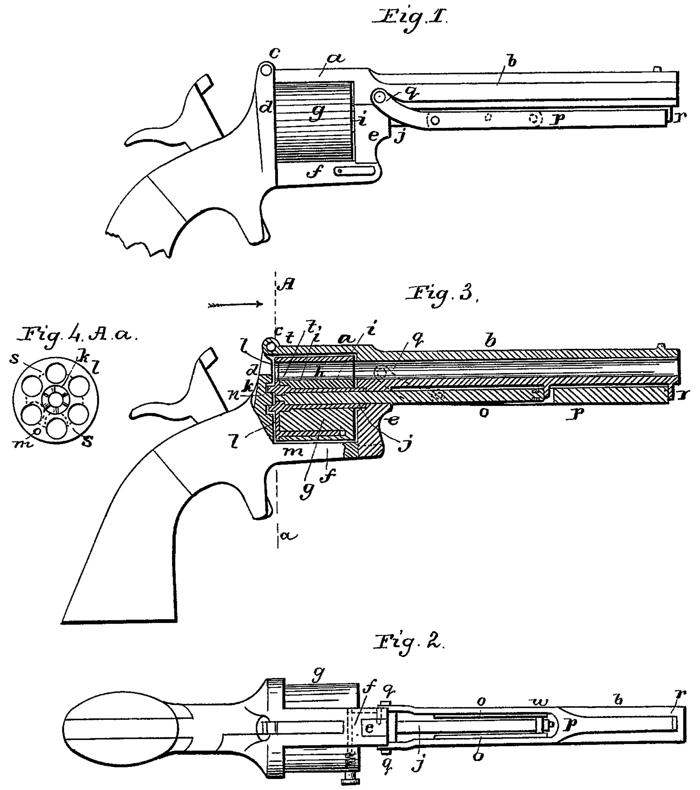
First. The barrel a, which is slightly rifled, slides on a central pin or axis, c, by means of a sleeve, b, and is guided and limited in its motion by means of a set-screw, d, penetrating a groove upon the under side of the central pin.
By removing the said screw the revolver maybe taken apart. With the sleeve is combined an eccentric operated by the lever e, whereby the sleeve may be fastened to or loosened from the central pin, which for that purpose is notched opposite the eccentric. When the lever is placed in position shown in Figure 1 the sleeve is secured to the pin, and when placed in position shown in Fig. 2 the parts may be separated, as shown. The movement of the lever is limited by means of a stud or set-screw, x. In the rear of the barrel there is a guard-plate, f, which covers the breech-chambers, so as to retain the balls and prevent their interfering with the rotation of the cylinder. With this guard-plate is combined another guard-plate or shield, g, for the purpose of protecting the hands against being burned by the fire or burning powder. A ramrod, h, is adapted to the side of the sleeve for the purpose to detach from the cylinders the remainder of exploded cartridges or to remove loaded cartridges, if necessary; and, lastly, to the tail-piece of the sleeve b there is secured a tenon which fits a corresponding recess in the main frame, and thus gives the necessary rigidity and strength to the arm.
Second. The cylinder k (shown detached in Figs. 3 and 4) contains six chambers, and is capable of revolution and sliding motion upon the fixed central pin, c. It is provided with a spring-catch, l, whereby it may be connected with the rotating breech-cap o by engaging with one of the six notches upon the circumference of the said breech-cap. On the rear part the cylinder is, moreover, provided with six indentations, m, and as many tenons, n, in contiguity with said indentations, the latter serving the purpose to effect connection, with the rotating breech-chamber by a bayonet catch, hereinafter described.
Third. The rotating breech-capo (shown detached in Figs. 5 and 6) is also free to revolve and to slide, together with the cylinder, upon the central pin. The piece is held within the frame of the revolver by means of a spring catch, v, which enters an annular groove, p, on the outside of the breech-cap. This piece is never removed, except when it is necessary to clean or to repair the arm.
Fourth. The stock which contains the actuating mechanism carries the pin or axis before mentioned, serving to connect the principal parts together, and an eccentric groove for connecting the barrel thereto. At the front it terminates in a cylindrical case, q, through an opening of which the hammers strikes the cartridge. The hammer is provided with a short projection fitting one of the notches— which I call “safety-notch”— of the rotating breech-cap, and has for effect to regulate with precision at each rotation the exact position of the said cap and the cylinder with respect to the barrel. The flat portion of the hammer strikes upon the primary pin, but will be prevented from exploding it if the projection do not come opposite the corresponding counter sink in the breech-chamber. The screw t holds the wood portions of the stock together upon the frame and incloses the mechanism of the arm. An important feature of this invention consists in the casing in and mobility of the breech-cap within the fixed or stationary breech-case q. According to the ordinary construction of revolvers the cylinder is liable to slide against the breech-plate, and by the effects of oxidation and dilation by heat of the metal cap of the cartridge to produce friction to an extent as to interfere with the functions of the arm. In this case, however, the explosion of the cartridge is effected against the breech-cap, it revolving with the cylinder, and consequently nothing can prevent or interfere with the rotation of the cylinder.
The loading of this revolver is effected by holding the stock with the left hand, while with the right hand the lever e is depressed into position shown in Fig. 2. The barrel is then pushed forward upon the central pin, c, and the cylinder detached from the breech-plate and also pushed forward, while the breech – plate remains behind in the fixed breech-case q. The arm is then held with the barrel pointing downward, and the chambers are charged. When this is done the cylinder is pushed back, and, engaging with the bayonet catch, is secured. The barrel is next pushed back, and the whole is locked by turning the eccentric into position shown in Fig. 1. The arm is now ready for use. To dismember the revolver, screw d is first removed, the eccentric lever d is then depressed, Fig. 2, and the barrel is drawn out. By a slight turn upon its axis the cylinder k becomes detached, and may then be taken out. The hammer is then raised, and, pressing on the trigger, the breech plate is disengaged and may be removed. The movable parts being thus removed, there remains the stock with its inclosed mechanism and the fixed pin and breech-case. Having thus described my invention, and the manner in which the same is or may be carried into effect, I claim—
1. The combination, in a revolver, of the following parts: the barrel, the cylinder, the breech-plate, and the stock, when the said parts are constructed as described, each being capable of being detached in the manner and for the purpose set forth.
2. In combination with the many-chambered cylinder and rotating breech-plate, the means herein described of locking and unlocking the same.
3. The combination of the rotating cylinder and breech-plate with a fixed breech-casing and its spring-locking device to hold the breech-plate in place without interfering with its rotary movements.
In testimony whereof I have signed my name to this specification before two subscribing witnesses.
A. GUERRIERO.
Witnesses:
Francs. Savareje Teftimone,
Charles Marsh.