
British 1608
LETTERS PATENT to Alfred Vincent Newton, of the Office for Patents, 66, Chancery Lane, in the County of Middlesex, Mechanical Draughtsman, for the Invention of “ Improvements nr Repeating Fire-arms.”— A communication.
Sealed the 2nd December 1856, and dated the 8th July 1856.
PROVISIONAL SPECIFICATION left by the said Alfred Vincent Newton at the Office of the Commissioners of Patents, with his Petition, on the 8th July 1856.
I, Alfred Vincent Newton, of the Office for Patents, 66, Chancery Lane, in the County of Middlesex, Mechanical Draughtsman, do hereby declare the nature of the said Invention for 41 Improvements nr Repeating Fire-arms/* to be as follows:—
This Invention relates to improvements on rotating breech fire-arms, the main object being to bring up the breech cylinder into close contact with the barrel after each partial rotation of the cylinder, and thus to prevent the lateral escape of fire (during a discharge) between the barrel and the cylinder.
The first feature of this Invention consists in the employment of a toggle connection between the cylinder or the rotating recoil shield and the stock, for the purpose of effecting a longitudinal or endway movement of the cylinder to SPECIFICATION in pursuance of the conditions of the Letters Patent, filed by the said Alfred Vincent Newton in the Great Seal Patent Office on the 8th January 1857.
TO ALL TO WHOM THESE PRESENTS SHALL COME, I, Alfred Vincent Newton, of the Office for Patents, 66, Chancery Lane, in the County of Middlesex, Mechanical Draughtsman, send greeting.
WHEREAS Her most Excellent Majesty Queen Victoria, by Her Letters Patent, bearing date the Eighth day of July, in the year of our Lord One thousand eight hundred and fifty-six, in the twentieth year of Her reign, did, for Herself, Her heirs and successors, give and grant unto me, the said Alfred Vincent Newton, Her special license that I, the said Alfred Vincent Newton, my executors, administrators, and assigns, or such others as I, the said Alfred Vincent Newton, my executors, administrators, and assigns, should at any time agree with, and no others, from time to time and at all times thereafter during the term therein expressed, should and lawfully might make, use, exercise, and vend, within the United Kingdom of Great Britain and Ireland, the Channel Islands, and Isle of Man, an Invention for “ Improvements nr Repeating Fire-arms,’* being a communication from abroad, upon the condition (amongst others) that I, the said Alfred Vincent Newton, by an instrument in writing under my hand and seal, should particularly describe and ascertain the nature of the said Invention, and in what manner the same was to be performed, and cause the same to be filed in the Great Seal Patent Office within six calendar months next and immediately after the date of the said Letters Patent.
NOW KNOW YE, that I, the said Alfred Vincent Newton, do hereby declare the nature of the said Invention, and in what manner the same is to be performed, to be particularly described and ascertained in and by the following statement, reference being had to the Drawings hereunto annexed and to the letters and figures marked thereon (that is to say):—
This Invention, as communicated to me from abroad, relates to fire-arms, in which the rotating many-chambered cylinder works upon an axle parallel with the barrel.
The first feature of the Invention consists in the employment of a toggle connection between the cylinder or the rotating recoil shield and the stock, for the purpose of effecting a longitudinal movement of the cylinder to make it clear the barrel in rotating, and to force it up into a tight connection therewith, after the rotating movement has been effected; the toggle connection being operated by means of a finger lever under the stock.
The second feature of the Invention consists in placing a regulating screw between the forward end of the above-mentioned toggle and the rotating recoil shield or cylinder, for the purpose of adjusting the connection between the cylinder and barrel.
The third feature of the Invention consists in combining the dog or catch, by which the rotation of the recoil shield and cylinder is effected, with the toggle, in such a manner that it is operated by the bending of the toggle to let the cylinder move back.
The fourth feature of the Invention consists in causing the cylinder, by its backsliding movement, to throw itself at one period into a stay ratchet relation^ ship, and at another period into a locked connection with a spring stopper, as will be herein-after described.
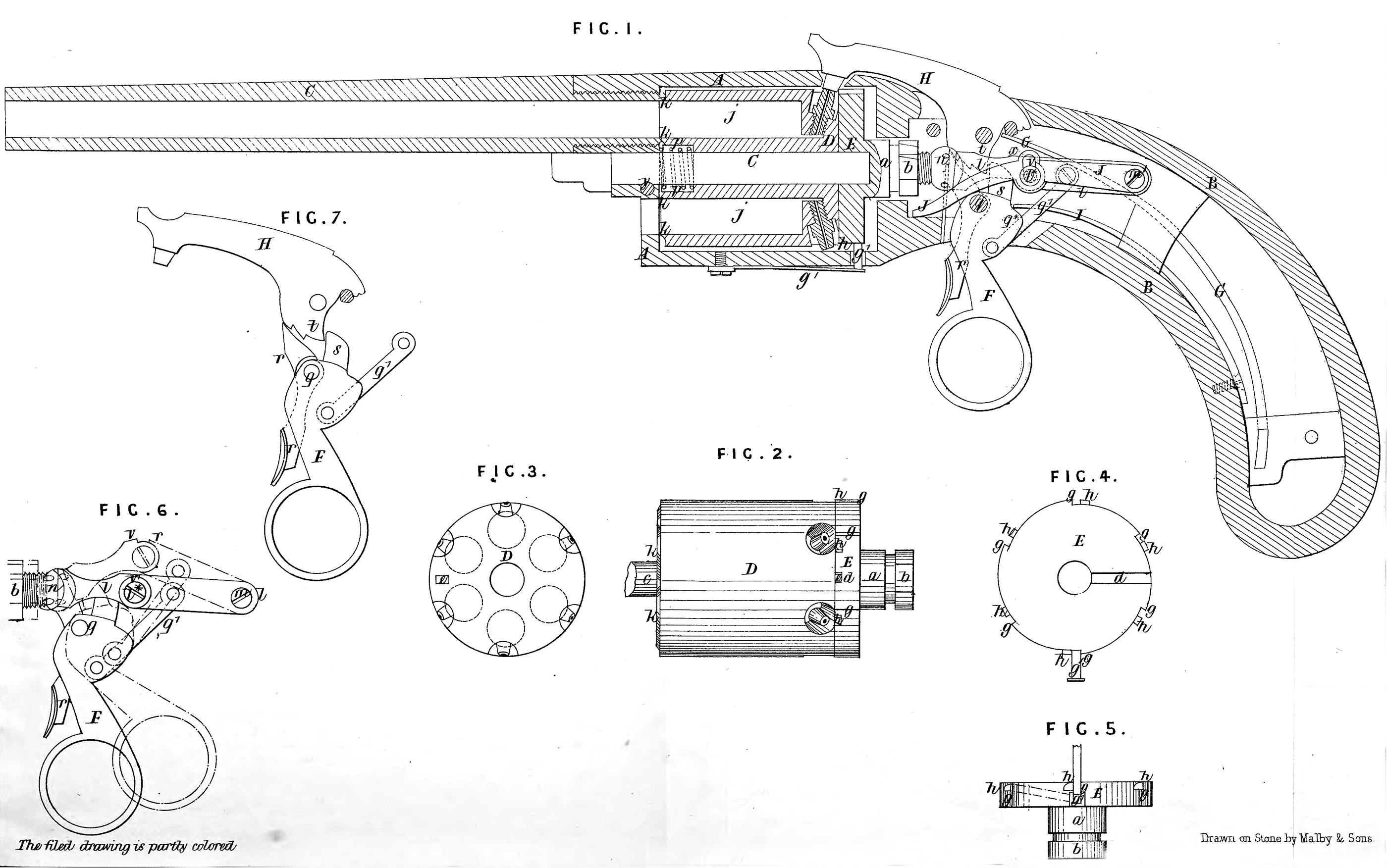
In the accompanying Drawings forming part of this Specification, Fig. 1 is a longitudinal central section of a pistol constructed according to the Invention ; Fig. 2 is a side view of the rotating chambered cylinder and rotating recoil shield detached from the pistol; Fig. 3 is a rear view of the cylinder; Fig. 4 is a front face view of the rotating recoil shield; Fig. 5 is a view of the same looking from underneath it, showing also the stopper; Fig. 6 is a side view of the toggle by which the cylinder is forced up to a tight connection with the barrel, shewing also its lever attachment; Fig. 7 is a side view of the hammer, the lever by which the cocking of the hammer and rotating of the breech are effected, and the trigger. Similar letters of reference indicate corresponding parts in the several figures.
A is the metal breech frame, which is made all in one piece with or attached to a metal frame B, which extends to the butt of the stock ; C is the barrel which is screwed into the breech frame A; D is the rotating chambered cylinder, and E the recoil shield. The recoil shield consists of a circular disc of steel or other metal, of the same diameter as the cylinder, having a journal a at back to fit in a bearing in the rear of the breech frame A. At the rear extremity of this journal is a circular ratchet 5, the number of whose teeth corresponds with the number of chambers j, j, in the cylinder; the ratchet is like that generally made on the cylinder for the purpose of rotating it, and is for rotating the recoil shield. The front face of the recoil shield is faced flat, to fit snugly up to the rear of the cylinder, which is also faced flat; the cylinder is bored centrally throughout to receive the arbor c on which it rotates, and the recoil shield has a hole bored to some depth from its front face to receive the extremity of the arbor, which, when inserted through the front of the breech frame A through the cylinder and into the hole in the recoil shield, and secured by a transverse pin /, keeps both the cylinder and recoil shield in place. In the front face of the recoil shield is a radial groove d, and from the rear end of the cylinder projects a pin e of such size as to fit the groove dt and by that means to connect the cylinder and recoil shield, so that the latter in rotating will give motion to the former. The above combination of the cylinder with a rotating recoil shield, allows the cylinder to be taken out by simply drawing the arbor c in a forward direction out of the cylinder, and sliding out the cylinder laterally from the frame; but care should be taken that, before drawing out the arbor, the groove d stands in a position lateral to the breech frame A to sallow the pin or projection e to slide out. When the cylinder has been taken out, the rotating recoil shield can be taken out by drawing it forward, to withdraw the journal a from its bearing in the back of the frame, to admit of which the exterior of the ratchet b must be made no larger than the journal a Every chamber j of the cylinder is furnished at its front end with a cone k, which extends a little beyond the front face of the cylinder, for the purpose of entering a conical seat in the rear of the barrel to prevent the escape of gas and the consequent loss of the force of the explosion; or, the same effect may be produced by making a seat around the front of the chamber to fit over a cone on the rear of the barrel; this makes it necessary for the cylinder to receive a backward longitudinal movement after every discharge and before the rotating movement to bring another chamber in line with the barrel takes place, and a forward movement after the rotation and before firing to bring the cone and seat into close contact to make a tight joint This movement, however, forms no part of this Invention, but only the mothod of producing the said movement by a toggle Z, Z1; Figures 1 and 6 shew this toggle, one end of which is connected by a pin m with the stocky frame B, while the other end is made with a concave seat or female centre to receive and form a bearing for the head of the screw n, which enters a female screw in the centre of the rear of the recoil shield. The relation between the recoil shield and the toggle is so adjusted by the screw n, that, when the toggle is straightened, as shown in Fig. 1, and, in black outline in Fig 6, at a time when a chamber is in line with the barrel, it drives up the recoil shield and cylinder, and holds the cone and seat tightly together, thus making a tight joint between the chamber and barrel; but by the bending of the toggle, as shown in red outline in Fig. 6, the recoil shield is allowed to be forced back by a springy? which is coiled round the arbor c between the front of the cylinder and the breech frame A and received within a cavity in the cylinder. The toggle is actuated to produce the above results by means of a finger lever F, see Figures 1, 6, and 7, which also serves the purpose of cocking the hammer; this finger lever works upon the same fixed pivot or fulcrum pin q as the trigger r ; it is connected with the toggle behind the joint pin l thereof, by means of a link q\ which causes it to bend the toggle when its lower end is drawn back, and straighten it when it is moved forward; the joint of the toggle being prevented descending beyond a straight position by shoulders on each part above the joint (see v, v, Fig. 6). The finger lever F is furnished with a rigid dog or catch s which is behind the tumbler t of the hammer H, and this dog is thrown forward by drawing back the lower end of the lever, and thus is caused to push forward the tumbler t and cock the hammer simultaneously with the bending of the toggle to let the cylinder come back.
The hammer is substantially like the hammer of a common gun or pistol, having the same notches in its tumbler for the sere of the trigger to fall into to hold it in full or half-cock ; the only difference from the common tumbler being, that the back part of the tumbler is made of a suitable form for the catch s to engage with it to effect the cocking. It is actuated when let off by the drawing of the trigger r by means of a mainspring G, which is arranged substantially like the mainspring of a common gun or pistol lock. The trigger r is substantially like the trigger of other fire-arms. It is partly received in a slot in the finger lever F* and the part which protrudes from the stock stands in front of the finger lever, so that the person using the arm can work the finger lever with the second finger, and the trigger with the first finger of his right hand. The finger lever F has a spring I applied to press upon a shoulder q* behind the pin q. This spring tends to draw down the joint of the toggle and straighten it, and when the shoulders v, v, are in contact, it keeps the toggle in a sufficiently rigid condition to preserve a tight and immovable connection between the cylinder and barrel. J is the dog or catch by which the ratchet b is operated upon to rotate the recoil shield and cylinder. This catch is hung upon the pin m, which attaches the toggle to the stock, and is provided with a slot
The periphery of the recoil shield is furnished with a number of ratchet teeth gt gy corresponding with the number of chambers in the cylinder. These ratchet teeth are set the same way as those of the ratchet b, and are for the purpose of engaging with a spring stopper g\ working through a hole in the breech frame to prevent the recoil shield and cylinder being returned by the catch J in its return movement. These teeth extend all across the periphery of the recoil shield. There are, also, upon the periphery of the recoil shield a similar number of stop pins h, h, arranged at such distances from the bottom of every tooth as to leave just room for the stopper gx to enter between them and the ends of the ratchet teeth, and, consequently, when the stopper falls between them,.it locks the cylinder, so that it cannot move in either direction. These pins are near the front of the recoil shield, and when the recoil shield and cylinder are in their forward position, the stopper occupies a position relatively to a ratchet tooth and stop pin, shewn in Figures 4 and 5. When the finger lever F is drawn backwards to cock the hammer and draw back and rotate the cylinder, the cylinder rotates so far before the recoil shield moves back far enough for the stop pin g1 to catch the stopper h, that the recoil shield will in the meanwhile carry the bottom stop pin past the stopper, after which the relative longitudinal and rotating movements of the recoil shield cause the stopper to describle on the periphery of the recoil shield, the lines shown in red in Fig. 5, so that when the rotating movement terminates, and the stopper slips over the tooth gf it falls between the tooth and stopper, and thus not only prevents the shield moving too far, but also prevents its being returned by any reaction that may be produced by its sudden stoppage. When the finger lever F is allowed to move forward, the stop pin h works clear of the stopper g\ as it is not required after the catch J begins to descend, for the action of that catch tends to throw the edge of the ratchet tooth g into contact with the stopper.
The same arrangement of ratchet teeth and stop pins might be used on the rear part of the periphery of the cylinder of a fire-arm made without the rotating recoil shield. The toggle movement might also be applied to such an arm. The toggle connection between the cylinder and stock effects the same result as has been before accomplished by a wedge, but it can be fitted at much less expense, and permits of the adoption of simpler mechanism for rotating the cylinder, besides enabling the whole of the lock to be made more compact.
Having now set forth the nature of the Invention, as communicated to me by my foreign correspondent, and explained the manner of carrying the same into effect, I wish it to be understood that, under the above in part recited Letters Patent, I claim,—
Firstly, the employment of a toggle connection l, l, between the cylinder or the rotating recoil shield and the stock, for the purpose of allowing and producing the longtudinal movement of the cylinder, to enable it to clear the barrel in revolving, and of forcing the cylinder up to the barrel to make a tight connection therewith, substantially as herein described.
Secondly, placing a regulating screw n between the front end of the toggle connection and the cylinder or recoil shield, substantially as described, for the purpose of adjusting the connection between the cylinder and barrel, without requiring a great degree of accuracy in the fitting of the toggle movement, and for the purpose of compensating for any wear.
Thirdly, connecting or combining the catch J by which the rotating motion of the recoil shield and cylinder is produced with the toggle connection l, l, in such a manner that it is operated by the bending of the toggle to allow the cylinder to move back, substantially as herein described.
Fourthly, though I do not claim of itself the use of a positive stop or catch to lock the cylinder after its rotation, as such connected by complicated devices with the trigger and otherwise, has before been done, nor yet claim the mere employment of an additional rachet to prevent back rotation of the cylinder. I do claim causing the cylinder, during the one portion of its longitudinal movement, to form a ratchet connection with a spring stopper gx, that admits of the cylinder’s rotation only in the one direction, but on the completion of the cylinder s rotating movement, and at the termination of the back longitudinal travel thereof, forms a positive stop to the cylinder by means of the ratchets g> g, and stop pins h, h, on the sliding cylinder or recoil shield, arranged and acting in concert with the stopper g\ essentially as described.
In witness whereof, I, the said Alfred Vincent Newton, have hereunto set my hand and seal, the Eighth day of January, in the year of our Lord One thousand eight hundred and fifty-seven.
A. V. NEWTON. (l.s.)
Witness,
J. W. Moffatt,
66, Chancery Lane.