
US 566393
UNITED STATES PATENT OFFICE.
ANDREW FYRBERG, OF WORCESTER, MASSACHUSETTS, ASSIGNOR TO IVER JOHNSON, OF SAME PLACE.
LOCK FOR REVOLVERS.
SPECIFICATION forming part of Letters Patent No. 566,393, dated August 25, 1896.
Application filed October 2, 1891. Serial No. 407,516, (No model.)
To all whom it may concern:
Be it known that I, ANDREW FYRBERG,a citizen of the United States, residing at Worcester, in the county of Worcester and State of Massachusetts, have invented certain new and useful Improvements in Firearms, of which the following is a specification, accompanied by drawings forming a part of the same and to which reference is herein made.
My invention relates to an improvement in the firing mechanism of firearms, and the object is to provide the firearm with a safety firing mechanism which will prevent the discharge of the firearm by any action of the hammer except as released by the trigger.
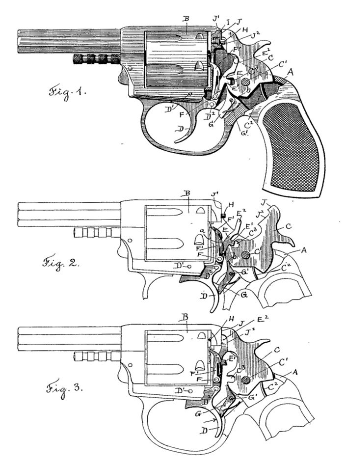
In the accompanying drawings, Figure 1 represents a firearm embodying my invention, a portion of the framework having been broken away in order to disclose the lock mechanism and the device embodying my invention, the several operating parts being shown in their normal position. Fig. 2 represents the firearm shown in outline with the hammer placed at full-cock, and Fig. 3 represents the same with the operating parts in the position assumed at the moment of discharge.
Similar letters refer to similar parts in the several figures.
In the accompanying drawings J have shown my invention as applied to a revolver of the usual form of construction. It is, however, – adapted to all firearms in which the discharge is effected by means of a lock mechanism.
In Fig. 1, A denotes the frame; B, the revolving chamber-cylinder; C, the hammer rotating upon the pivot C’and actuated by the mainspring C2.
D denotes the trigger, turning upon a pivot D’ and carrying, pivoted thereto at D2, the pawl E, provided with a spur E’, engaging the notch C3 upon the hammer.
Pivoted upon the pawl E at F is a cylinder pawl F’, by which the cylinder B is rotated in the usual manner. A blade-spring a, acting jointly upon the pawls E and F’, serves to bring them into engagement with the hammer C and cylinder B, respectively. The hammer is provided with a notch b, which is engaged by the sear G, thereby holding the hammer in position at full-cock. So much of the construction and operation as relates to that portion of the lock mechanism already described will be readily understood, as it is substantially the same as is now in common use.
My invention relates to the mechanism, hereinafter described, by which the discharge of the firearm is prevented by any action of the hammer independently of the movement of the trigger. Sliding in the frame is a firing-pin H, arranged to be driven against the cartridge-head by the action of the hammer and retracted by the spiral spring I in the usual manner. The hammer C is provided with a face J, which is brought against the frame at J’ in the operation of discharging the firearm, thereby limiting the movement of the hammer. Below the face J the hammer is cut away, forming a face J2, which clears the end of the firing-pin H when the hammer is in the position shown in Fig.1. When the hammer is brought to the position of full-cock and retained by the sear G, it is released by the backward motion of the trigger D against the sear G, causing it to rock upon the pivot G’ and releasing the hammer C, which is carried into the position shown in Fig. 3 by the action of the mainspring C2. The rearward motion of the trigger D in the operation of releasing the hammer carries the pawl E upward, so as to bring the end E2 into the path of the hammer and between the face J2 and the rear end of the firing-pin H, so that the blow of the hammer will be received by the end E2 of the pawl E, and through the end E2 will cause the firing-pin to be pushed forward against the cartridge-head.
When the trigger D is released, it is carried forward into the position shown in Fig. 1 by a blade-spring held in the frame and not shown in the accompanying drawings,as its construction and operation will be fully understood. The forward movement of the trigger D into the position shown in Fig. 1 will be pressed, the pawl E withdrawing the end E2 from between the face J2 of the hammer and the end of the firing-pin H and bringing the spur E’ into proper position to engage the notch C3 in the hammer as the pawl E is thrown backward by the action of the spring F’, causing it to assume the position represented in Fig. 1.
If the hammer C be raised and released from any position other than a full-cock, the blow will be received upon the face of the frame J’ and the face J of the hammer without moving the firing-pin, for the reason that the end E2 of the pawl E will not have been lifted high enough to be caught between the face J2 of the hammer and the end of the firing-pin H; but in case the hammer is raised to a full-cock it then becomes locked by the action of the sear G and prevented from discharging the firearm except as it is released by the rearward movement of the trigger D, which also serves to elevate the end E2 into the path of the face J2 of the hammer and interposing it between the hammer and the firing-pin H.
It will be obvious that the essential feature of my present invention as herein described does not depend upon the specific construction and arrangement of the operating parts comprising the lock mechanism. For example, in the mechanism shown the hammer-lifting pawl E is extended at E2 to be interposed between the face J2 and firing-pin H; but the part E, which in the present construction forms a single piece, might be made in separate pieces and hinged to the trigger, or a separate lifting-pawl engaging the hammer could be pivoted upon E, and instead of the notch C3 engaged by a spur E’ a shoulder or tooth might be formed on the tumbler of the lock adapted to be engaged by a lifting-pawl.
I do not confine myself to a spring-retracted firing-pin, as shown, the essential feature of my present invention consisting of a piece interposed between the face of the hammer and the firing-pin at the releasing of the hammer by the rearward movement of the trigger and the withdrawal of said interposed piece, except upon the releasing of the hammer by the trigger, and in forming the face of the hammer so as to clear the firing-pin when the interposed piece has been withdrawn.
I am aware that the firing-pin has been provided with a shoulder upon one side of the pin adapted to be struck upon its rear face by the hammer, but which is capable of being carried out of the path of the hammer by the rotation of the firing-pin itself, and I do not therefore herein claim such a construction. The firing-pin in my device is capable of a longitudinal movement only, forward as impelled by the blow from the hammer and rearward as retracted by a spring, thereby simplifying the construction of the lock, and I interpose an independent piece between the face of the hammer and the rear end of the firing-pin, whereby the force of the blow exerted by the hammer is exerted directly in a line coincident with the axis of the firing-pin, which is not the case when the pin is struck upon a shoulder projecting from the side of the pin.
What I claim as my invention, and desire to secure by Letters Patent, is—
1. In a firearm, the combination with the frame of a firearm, of a firing-pin, a pivoted hammer provided with the faces J and J’, with the face J arranged to strike the frame and receive the blow of the hammer and with the face J2 in alinement with the firing-pin, an interposing piece, and means for inserting said interposing piece between said firing-pin and said face J2 of the hammer, substantially as described.
2. In a firearm, the combination with a firing-pin and a hammer arranged to clear said firing-pin, and a pivoted trigger and a piece hinged to said trigger and interposed between said hammer and said firing-pin by the movement of the trigger in releasing the hammer, whereby the blow of the hammer is made to actuate said firing-pin, substantially as described.
3. The combination of a firing-pin, a hammer provided with a notch or tooth by which it is engaged by a sear when at full-cock, a sear engaging said notch, or tooth, a trigger by which said sear is disengaged and the hammer released, and an interposing piece operatively connected with said trigger, and arranged to be carried between said firing-pin and the face of the hammer by the action of said trigger in releasing said hammer, substantially as described.
4. The combination of the firing-pin, hammer arranged to clear said firing-pin and provided with a notch to be engaged by a lifting-pawl and a notch or tooth to be engaged by a retaining-sear when the hammer is at full-cock, a sear engaging the hammer, a trigger operating to disengage said sear, a lifting-pawl carried by said trigger and engaging the hammer, said lifting-pawl having its free end extended between the face of the hammer and the firing-pin as the sear is disengaged from the hammer, substantially as described.
ANDREW FYRBERG.
Witnesses:
IVER JOHNSON,
RUFUS B. FOWLER.