
US 511620
UNITED STATES PATENT OFFICE.
IVER JOHNSON AND OSCAR MOSSBERG, OF FITCHBURG, MASSACHUSETTS; SAID MOSSBERG ASSIGNOR TO SAID JOHNSON.
BARREL-STRAP CATCH FOR REVOLVERS.
SPECIFICATION forming part of Letters Patent No. 511,620, dated December 26, 1893. Application filed March 6, 1893. Serial No, 464,850. (No model.)
To all whom it may concern:
Be it known that we, IVER JOHNSON, a citizen of the United States, and OSCAR MOSSBERG, a subject of the King of Sweden and Norway, residing at Fitchburg, in the county of Worcester and State of Massachusetts, have invented a new and useful Improvement in Firearms, of which the following is a specification, reference being had to the accompanying drawings, forming a part of the same, and in which—
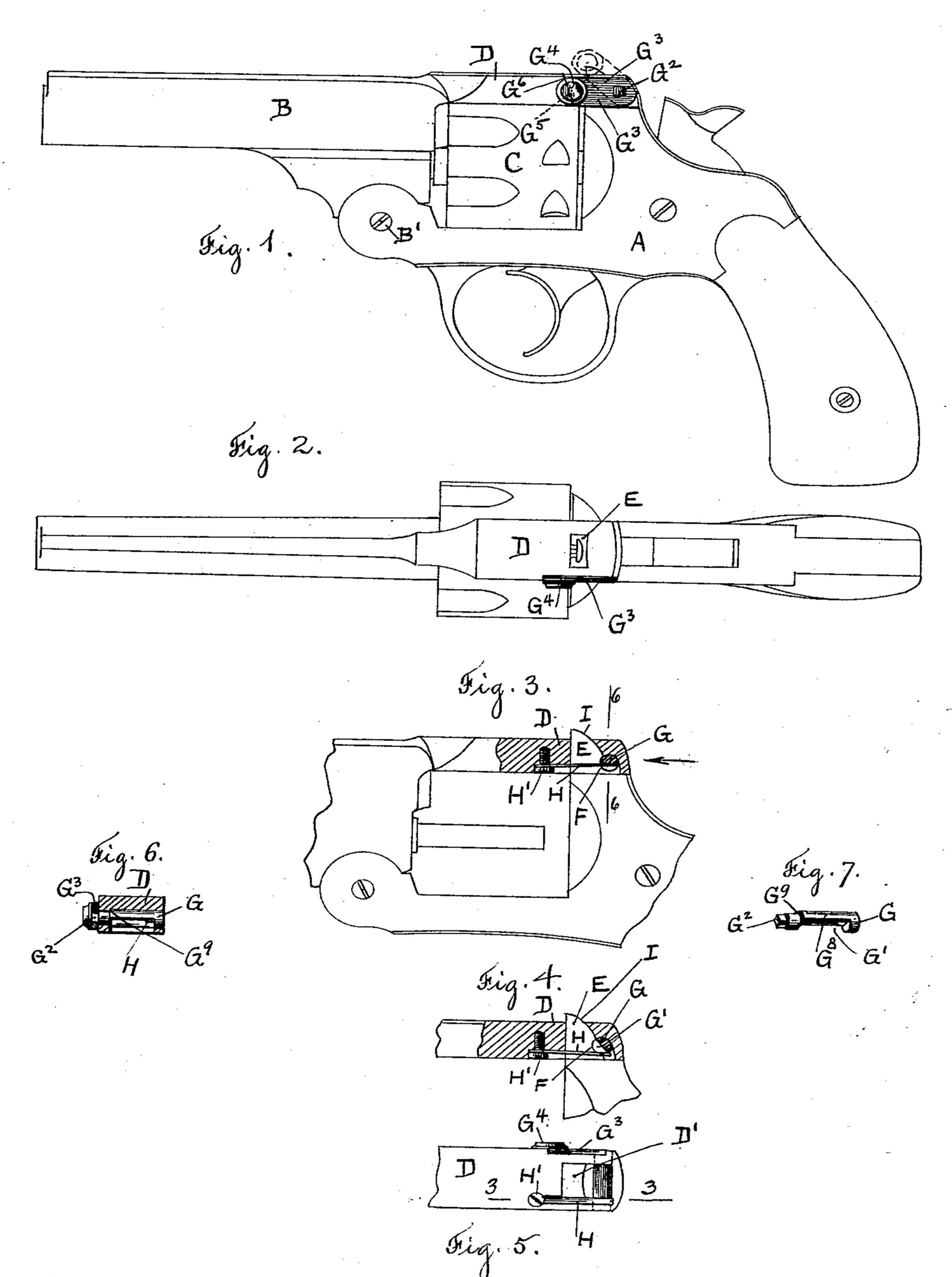
Figure 1 represents a side view of a revolving fire-arm embodying our invention. Fig. 2 is a top view of the same. Fig. 3 is a side view of the barrel strap shown in section on line 3, 3, Fig. 5, in order to disclose the latch and its connected actuating spring, which are shown in position when the latch has engaged the post. Fig. 4 is a side view of the barrel strap shown in section on line 3, 3, Fig. 5, but with the latch disengaged from the post. Fig. 5 represents the underside of the barrel strap showing the rotating latch and its connected spring. Fig.6 represents a vertical sectional view of the barrel strap on line 6, 6, Fig. 3, and Fig.7 is a detached view of the rotating spindle journaled in the barrel strap.
Similar letters refer to similar parts in the different figures.
Our present invention relates to the latching mechanism by which the barrel strap is attached to the post of the fire-arm and it will be readily understood by the following description and reference to the accompanying drawings, in which—
A denotes the frame of the fire-arm, B the barrel pivoted to the frame at B’ and extending rearwardly over the cylinder C forming the barrel strap D, which is provided with a mortise D’ at its rear end to receive the post E projecting upwardly from the frame A; the mortise and post being so arranged, that when the barrel is rocked upon the pivot B’ and brought into its normal position as represented in Fig. 1, the mortise of the barrel strap will inclose the post, to which the barrel strap is automatically locked by the latching mechanism forming the subject of our present invention.
The rear side of the post E is provided with a semi-circular notch F, and journaled within the barrel strap D, is a rotating spindle G having its central portion cut away, forming a flat surface G’ and provided at one end with the tenon G2, to which is attached a plate G3 having a raised boss, or knob G4. Held within a recess in the under side of the barrel strap is a blade spring H attached to the strap by a screw H’, with the free end of the spring bearing against the flat side of the spindle G, so the tension of the spring will be applied to rotate the spindle and hold it in the position represented in Figs. 1 and 3, with the beveled end G5 of the lever G3 resting against the shoulder G6.
The rear side of the post E is beveled, or slightly rounded, as at I, so that when the barrel strap is brought over upon the post, the surface I, as the post enters the mortise D’, will bear against the flat side G’ of the rotating spindle, causing it to be rocked from the position shown in Fig. 3 to the position shown in Fig. 4 and allow the post to enter the mortise. When the semi-circular notch F is brought opposite the spindle, as shown in Fig. 4, the spindle will be rotated by the pressure of the spring H, causing the semi-cylindrical portion G8 of the spindle to enter the semi-circular notch F as shown in Fig. 3, thereby locking the barrel strap in position.
When it is desired to disengage the barrel strap from the post, the lever G3 is raised, as represented by the broken lines at J, Fig. 1, rotating the spindle G from the position shown in Fig. 4 to that shown in Fig. 3 and releasing the barrel strap and allowing the barrel to be rocked upon the pivot B’ against the tension of the spring H.
The latching mechanism, forming the subject of our present invention, is exceedingly simple in construction, requiring only a drilled hole through the strap to receive the rotating spindle and a milled recess to receive the blade spring. The rotating spindle is held in position by the shoulder G9 and by the lever G8 riveted upon the tenon G2, or a groove can be formed in the spindle to receive the end of a pin held in the barrel strap, or any known means employed whereby the spindle can be held from longitudinal movement. The spring H is easily replaced without the removal of any other portion of the latch and the spindle G is rotated by the upward movement of the lever G3, so that the pressure upon the lever G3 to carry it into the position shown in dotted lines will also serve to lift the end of the barrel strap D off the post E.
What we claim as our invention, and desire to secure by Letters Patent, is—
1. The combination with the barrel strap, provided with a mortise to receive the post and a post provided with a notch, of a rotating spindle journaled transversely in said strap in the plane of said notch and adapted to engage said notch by a partial rotation of said spindle and a spring applied to rotate said spindle and carry it into engagement with said notch, substantially as described.
2. The combination with a barrel strap and a post provided with a semi-circular notch, of a spindle journaled transversely in said strap and concentrically with said notch, and having one side cut away to allow the post to pass and a spring applied to rotate said spindle and carry it into said notch, substantially as described.
3. The combination with the barrel strap, of a fire arm provided with a mortise to receive a post, of a post entering said mortise and having a semi-circular notch, a spindle journaled transversely in said post and cut away upon one side to allow the post to pass, a spring applied to said spindle to rotate the same and carry it into said notch, and a lever extending radially from said spindle, whereby it is rocked to release the barrel strap, substantially as described.
Dated this 27th day of February, 1893.
IVER JOHNSON,
OSCAR MOSSBERG.
Witnesses:
HANNAH E. CALLANAN,
CHARLES FE. BAKER.