
US 505918
UNITED STATES PATENT OFFICE.
IVER JOHNSON AND ANDREW FYRBERG, OF WORCESTER, MASSACHUSETTS; SAID FYRBERG ASSIGNOR TO SAID JOHNSON.
REVOLVER.
SPECIFICATION forming part of Letters Patent No. 505,918, dated October 3, 1893.
Application filed December 31, 1888. Serial No. 294,986. (No. model)
To all whom it may concern:
Be it known that we, IVER JOHNSON and ANDREW FYRBERG, citizens of the United States, and residents of Worcester, in the county of Worcester and State of Massachusetts, have invented certain new and useful Improvements in Revolving Firearms, of which the following is a specification containing a full, clear, and exact description of the same, accompanied by drawings forming a part of the specification and showing in elevation and in several detailed views those portions of a revolver which embody the essential features of our invention.
The objects of our invention are, to provide means for locking the revolving cylinder and holding the same from turning while the cartridges are being exploded; to provide means for locking the revolving cylinder upon its spindle and thereby preventing its longitudinal movement thereon; to provide means whereby the barrel strap is locked upon the catch-post; to provide means for preventing the explosion of the cartridge unless the barrel strap is securely locked to the catch-post; and further to provide means for retaining the hammer in a position which shall allow the barrel strap retaining latch to be moved for the purpose of releasing the strap from the catch-post; and our invention consists, first, in a latching or locking device pivoted upon and carried by one of the operating parts of the lock, and actuated to withdraw from the notches in the cylinder by means of its engagement, or contact with a fixed portion of the fire-arm; second, in the construction and arrangement of the locking device and the parts forming the same, whereby its motion is reversed and it is made to engage the cylinder and hold it from rotation on its spindle; third, in the sliding spring-actuated pin carried in the barrel strap, with its latch pin pivoted thereon; fourth, in the latching mechanism by which the barrel strap is attached to the catch-post; fifth, in the arrangement of a pivoted hammer and a pivoted latching mechanism for attaching the barrel strap to the catch-post, said latching mechanism and said hammer moving in a common path, whereby they are caused to collide and arrest the hammer, and thereby prevent the explosion of the cartridge, except when the barrel strap is securely latched upon the catch-post, and our invention further consists, sixth, in the construction and arrangement of the devices by which the hammer is operated, whereby it is held out of the path of catch-post latch and in a position to prevent the premature explosion of the cartridge.
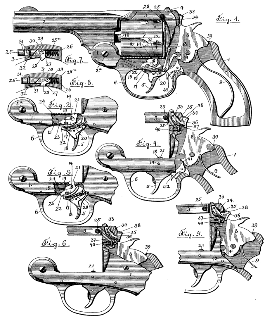
Referring to the accompanying drawings, illustrating such portions of a revolving fire-arm as embody our invention:—Figure 1 represents in side view a portion of a revolver, a part being shown in sectional view in order to disclose the mechanism by which the cylinder is locked against a rotary motion upon its spindle, the locking mechanism being shown in its normal position. Fig. 2 represents a portion of a revolver with a part of the frame inclosing the cylinder locking mechanism removed and showing the locking mechanism as withdrawn from engagement with the cylinder. Fig. 3 represents the same parts as are shown in Fig. 2, but with the locking mechanism as having re-locked the cylinder from its position as shown in Fig. 2. Fig. 4 denotes a portion of the revolver showing its hammer raised and retained by the sear in order to remove the hammer from the path of the catch-post latch. Fig. 5 denotes a portion of the revolver with the hammer held by the catch-post latch from acting upon the firing pin, the portion of the frame covering the hammer having been removed and the barrel strap being shown in longitudinal sectional view. Fig. 6 represents the same portion as shown in Fig. 5, but with the hammer under the catch-post latch. Fig. 7 represents a transverse sectional view of the barrel strap illustrating the construction and operation of the latching mechanism by which the cylinder is held from longitudinal movement upon its spindle. Fig.8 represents the same parts as are shown in Fig. 7, but with the latching mechanism in a different position.
Similar figures refer to similar parts in the several views.
In the accompanying drawings, 1 denotes the frame; 2 the barrel; 3 the barrel strap; 4 the catch-post; 5 the trigger; 6 the trigger guard; 7 the cylinder; 8 the hammer and 9 the hammer spring. The construction and arrangement of all these parts being well understood by those conversant with this class of fire arms a detailed description is deemed unnecessary.
The cylinder 7 turns upon a spindle 10 and is provided with a series of notches 11, which are successively engaged by the cylinder locking mechanism for the purpose of holding the cartridge chambers successively in alignment with the bore of the barrel 2 in the common and well known manner, the cylinder being turned upon its spindle 10 with an intermittent motion by means of the cylinder actuating mechanism comprising a series of ratchet teeth 12 upon the cylinder 7 and a pawl 13 pivoted to the trigger 5 and operated in the usual manner by the motion of the trigger in the operation of discharging the revolver.
The trigger 5 is pivoted upon a pin 14 held in the frame 1 and is held in its normal position by the trigger spring 15, acting against the rigid portion of the frame of the revolver, and exerting an upward pressure upon the shoulder 16 of the trigger. Pivoted upon a pin 17 and within a vertical mortise in the trigger is a cylinder stop 18 having an oblong hole or slot 19, through which the pivotal pin 17 passes. The stop 18 is acted upon by a spring 20, which serves to carry the curved catch end 21 upward through a slot in the frame and into one of the notches 11 in the cylinder 7, and also to press the stop 18 to the left, Fig. 1, as far as permitted by the pin 17 in the slot 19. The upward movement of the catch end 21 is limited by the contact of the stop 18 with the pin 14. The opposite end 22 of the stop18 rests upon the corner 23 of the trigger guard 6, or other fixed point of the revolver and as the trigger is moved back in the operation of discharging the revolver the pin 17 is depressed and as the end 22 is held from moving downward by means of its engagement with the corner 23 of the trigger guard, the catch end 21 will be depressed withdrawing the end 21 from its engagement with the cylinder and bringing the cylinder stop 18 into the position shown in Fig. 2, and releasing the cylinder, so that it is free to be turned by the cylinder actuating mechanism in the usual manner. The continued backward motion of the trigger 5, serves to withdraw the end 22 from the corner 23 of the trigger guard and permitting the spring 20 to carry the catch end 21 upward through the slot in the frame as shown in Fig: 3, and into the next succeeding notch upon the cylinder, which has been brought into the proper position by the action of the cylinder actuating mechanism, again re-locking the cylinder and holding it from turning as the further continued backward motion of the trigger effects the release of the hammer and the consequent discharge of the revolver. As the trigger 5 is again released it is moved forward into its normal position as shown in Fig. 1, by the action of the trigger spring 15, and as the cylinder stop 18 is carried from its position shown in Fig. 3 to that shown in Fig. 1, the curved edge 24 is brought against the corner 23 of the trigger guard and the cylinder stop is forced to the right and against the tension of the cylinder stop spring 20, permitting the end 22 to pass the corner 23 of the guard 6, when the action of the spring 20 will force the stop 18 to the left and into its normal position as shown in Fig.1. The cylinder 7 is thus released during a short period to allow the cylinder to be turned by the action of the cylinder pawl 13, and again locked | prior to and during the release of the hammer and the discharge of the cartridge through the operation of mechanism, shown in the drawings, but not herein described in detail as its construction and operation is old and forms no part of our present invention.
Instead of employing the corner 23 of the trigger guard as a fulcrum to produce a rotation of the cylinder stop about its pivotal pin and depress the catch end 21, a pin held in the frame of the revolver or any fixed portion of the revolver can be utilized for that purpose. The employment of a cylinder stop actuated by a spring and having a rocking motion upon its pivotal pin is not new, neither is it new to employ a cylinder stop having a rocking and sliding motion upon its pivotal pin, as such stops have been long in use, but it has been usual to pivot such stops upon a pivotal pin or a fixed point held in the fixed portion of the fire arm and to actuate them by the backward motion of the trigger either directly or through the intervention of intermediate mechanism and against the tension of a spring applied to the cylinder stop. Such a construction was shown in the patent to Sweet, dated December 10, 1878, No. 210,725, in which the stop was rocked upon the fixed pivotal point on the bottom of the recoil shield. Such a construction we do not herein claim.
The essential feature of our present invention consists in placing the cylinder stop upon the trigger itself and employing a fixed fulcrum with relation to which the cylinder stop is moved by the backward motion of the trigger. By this arrangement the cylinder stop is attached to the trigger and both held in the frame by the pivotal pin 14, thereby reducing the number of parts attached individually to the frame of the revolver. The cylinder is held from longitudinal movement upon its spindle by means of the mechanism shown in Figs. 7 and 8 and consisting of a sliding pin 25 held in a transverse cylindrical chamber 25a in the strap 3 and projecting from the side of the strap to allow it to be pushed in against the tension of the spiral spring 26 acting against the end wall of the cylindrical chamber in the strap 3. A short mortise 27 is made through the central portion of the strap and communicating with the chamber 25a. Through the mortise 27 is placed the latch 28 having its inner end hooked at 29 and inclosing a projecting pin 30 in the side of the sliding pin 25. The sliding pin is provided with shoulders 31, 31, between which is a pin 32 held in the strap 3 and entering the chamber 25a, by means of which the sliding motion of the pin 25 is limited. As the pin 25 is pushed into the chamber 25a, against the tension of the spring 26, the hooked end of the latch 28 is moved transversely to the strap 3 and the latch itself drawn into the chamber until its outer and projecting end becomes flush with the under side of the strap 3, as shown in Fig. 8. When the sliding pin 25 is released, the action of the spiral spring 26 forces the sliding pin and also the hooked end of the latch, reversing their motion and pushing the latch 28 through the mortise 27 and causing its outer end to project over the end of the cylinder, thereby locking it against any longitudinal movement upon its spindle 10. The latch 28 is slightly curved and the side walls of the mortise 27 in contact with the curved edges of the latch are made to conform in a degree in order to facilitate the sliding motion of the latch. The hooked end of the latch is open at one side and the spring 26 bears against the hooked end of the latch to force the latch outward, simultaneously with the outward sliding motion of the pin 25. The strap 3 is provided with a mortise 33, through which the catch-post 4 passes when the strap is locked upon the post in the usual manner common in fire arms of this class.
Pivoted within a recess in the catch-post 4 is a latch 34, provided with a shoulder 35 adapted to engage a corresponding shoulder 36 upon the strap 4, and within the mortise 33, and also having a spring 37 placed beneath the latch 34 to raise the same into engagement with the shoulder 36. The free end of the latch is formed into a thumb piece 38, entering, when the latch is depressed, into the slot 39 in the frame 1 through which the hammer is moved by the hammer spring 9 in the operation of discharging the revolver. When the strap 3 is attached to the post 4 by means of the latch 34,the hammer 8 passes beneath the free end of the latch or thumb piece 38, in the act of exploding the cartridge and as the hammer is slightly raised from contact with the firing pin 40 as is common in what are known as re-bounding hammers, the thumb piece 38 extends over the space in front of the hammer closing the same against the admission of dirt, the hammer occupying the position shown in Figs. 1 and 6, in which the parts named are shown in their normal positions. In order to release the strap 3 from the post 4 by the depression of the latch 34 it will be necessary to withdraw the hammer and retain the same in a position out of the path of the thumb piece 38. This might be accomplished by bringing the hammer to a full or half cock, but as these positions would incur the liability of a premature discharge of the revolver, we effect the desired purpose by forming a slight notch 41 in the hammer tumbler to be engaged by the sear 42 and retain the hammer in the position shown in Fig. 4 or raised just far enough to allow the latch 34 to be depressed and the strap 3 released from the post 4. The notch 41 is preferably V shaped with its corners slightly rounded in order to obviate the clicking sound when the hammer is raised. As the strap 3 is brought upon the post 4 by rocking the barrel 2 upon the pivotal pin 2a, by which it is pivoted to the frame 1, the wall of the mortise 33 pressing upon the latch 34 will serve to depress the same, provided the hammer is withdrawn from the path of the latch, until the shoulder 35 has passed the shoulder 36 on the strap, when the spring 37 will raise the latch, causing the strap 3 to be engaged by and securely locked upon the catch-post 4.
If the strap 3 is not depressed far enough to allow the spring 37 to raise the latch 34 and engage the strap, then the free end of the latch will be held in the path of the hammer, in the operation of discharging the revolver, and the hammer will be arrested in its forward movement as impelled by the hammer spring 9 and the discharge of the cartridge prevented. The latch 34, it will be seen, performs a double service besides the obvious one of attaching the barrel strap to the catch-post of the revolver, viz., that of a dust guard to prevent the admission of dust or dirt to the space in front of the hammer as it is raised from its contact with the firing pin, and also to act as a safety guard to prevent the discharge of the revolver in case the strap is brought into position upon the catch post, bringing the cartridges in position to be exploded by the impact of the firing pin, but without securely locking the barrel strap upon the catch-post; and this latter object we accomplish without reference especially to the specific form of construction embodied in the latching mechanism, as that might obviously be changed, but by arranging the latching mechanism with reference to the hammer so that the hammer and a moving part of the latching device shall occupy a common path and by which the forward movement of the hammer is arrested unless the latching device occupies its normal position in the engagement of the barrel strap upon the catch-post.
We do not claim broadly the employment in a revolver or other fire arm of a dust shield by which the admission of dust or dirt to the space in front of the rebounding hammer is prevented, as such was before known, but
What we do claim, and desire to secure by Letters Patent, is—
1. Ina revolving fire arm, the combination with a revolving cylinder, and a trigger pivoted in the frame of the fire arm, of a cylinder stop 18 pivoted midway its length upon said trigger and having one end adapted to engage said cylinder and its opposite end arranged to be held by a fixed stop, while the center of the cylinder stop is being moved in a circular arc by the angular movement of the trigger, and a fixed stop arranged to engage the end of said cylinder stop, substantially as described.
2. In a revolving fire arm, the combination with a revolving cylinder and a trigger pivoted in the frame of the fire arm, of a cylinder stop 18 pivoted upon, and carried by said trigger and provided with an upwardly curved end 21 adapted to engage said cylinder and also with a projecting end 22 adapted to engage with a fixed stop,and a fixed stop 23, said cylinder stop being pivoted on said trigger between the ends 21 and 22 and a spring 20 applied to said cylinder stop to carry the end 21 into engagement with the cylinder, substantially as described.
3. In a revolving fire arm, the combination with a revolving cartridge cylinder provided with a series of notches and a pivoted trigger, of a cylinder stop pivoted upon.and carried by said trigger, said stop having an oblong opening or slot through which its pivotal pin passes and.a spring with its tension applied to said stop to carry one of its ends into the notches in said cylinder and also to move said stop longitudinally in one direction in a line parallel with the major axis of said oblong opening, or slot, substantially as described.
4. In a revolving fire arm, the combination with a pivoted trigger and a revolving cartridge cylinder provided with a series of notches, of a cylinder stop pivoted upon and carried by said trigger and having an oblong opening or slot through which its pivotal pin passes, a spring with its tension applied to said cylinder stop to rotate said stop upon its pivot in one direction and also to move said stop in one direction in a line parallel with the major axis of said oblong opening or slot, a fulcrum arranged in the path of said cylinder stop as it is carried by said trigger, whereby the stop is rotated and the cylinder released, and a curved edge or cam surface upon said stop whereby it is slid upon its pivotal pin and against the tension of its spring to allow the stop to pass said fulcrum during the reverse or forward. motion of the trigger, substantially as described.
5. In a revolving fire arm, the combination with a pivoted trigger having a vertical mortise and with a revolving cartridge cylinder having a series of notches, of a cylinder stop 18 pivoted in said mortise in the trigger and provided with a catch end 21 adapted to enter the notches in the cylinder, with an oblong opening or slot 19 through which the pivotal pin 17 of the stop passes and also with a cam surface 24, a fixed fulcrum 23 and a spring 20 held within said trigger mortise and acting against said stop to rotate it in one direction and carry its catch end into the cylinder notches and also to move said stop endwise in one direction upon its pivotal pin, all arranged and operating, substantially as described.
6. In a revolving fire arm, the combination with a pivoted trigger and a cylinder provided with notches, of a cylinder stop pivoted upon said trigger and having a rounded catch-end adapted to enter the notches in said cylinder and a spring with its tension applied to said stop to carry its catch-end into said notches, and a pin arranged in the path of said stop whereby its motion is limited as actuated by said spring, substantially as described.
7. In a revolving fire arm, the combination with a pivoted trigger and a revolving cylinder provided with a series of notches, of a cylinder stop pivoted upon and carried by said trigger a spring with its tension applied to said stop to impart to said stop a rotary and an endwise motion in one direction, a fulcrum placed in the path of said stop as and for the purpose specified and a trigger spring with its tension applied to said trigger to reverse its motion, substantially as described.
8. The combination with a pivoted hammer, a catch post and a barrel strap having a mortise to receive said catch post, of a latch pivoted upon said catch post and having a shoulder adapted to engage a corresponding shoulder upon said barrel strap, a spring actuating said latch and a thumb piece formed on said latch and extending rearward over said pivoted hammer when in its normal position to serve as a dust shield, the free end of said latch entering the path of said hammer when the latch is depressed to release the barrel strap substantially as described.
9. The combination with a hammer pivoted in the frame, a catch post and a barrel strap having a mortise to receive said catch post, of a latch by which said barrel strap is held upon said catch post said latch being so arranged that it is moved in the operation of releasing the barrel strap, into the path of the hammer in the operation of discharging the fire arm, whereby said latch is made to serve as a safety check to prevent the discharge of the fire arm when the barrel strap is unlatched from the catch post, substantially as described.
10. The combination with a pivoted hammer and hammer spring, a catch post and a barrel strap having a mortise to receive said catch post of a spring actuated latch pivoted upon said catch post and having a shoulder arranged to automatically engage a corresponding shoulder upon said barrel strap by the action of its spring, the shoulder upon said barrel strap as the strap is carried upon the catch post, serving to depress said pivoted latch and carry it into the path of the hammer in the operation of discharging the fire arm, substantially as described.
11. The combination with a catch post and a barrel strap latched to said catch post and a hammer pivoted in the frame and having a hammer actuating spring and connected mechanism by which said hammer is released to the action of said hammer actuating spring substantially as described, of a safety check, consisting of a piece pivoted upon said catch post and actuated by the operation of latching the barrel strap upon the catch, whereby said pivoted piece is carried into the path of the hammer in the operation of discharging the fire arm, thereby arresting the motion of the hammer, substantially as described.
12. The combination with a catch post and barrel strap, of a pivoted latch, by which said strap is locked upon said post, a pivoted hammer, said latch as it is depressed to disengage the barrel strap moving into the path of said hammer as it is brought against the firing pin, said hammer having a notch in its tumbler arranged to be engaged by a sear, by which the hammer is held in position to allow the latch to be depressed, and a retaining sear, substantially as described.
IVER JOHNSON,
ANDREW FYRBERG.
Witnesses:
Rourus B. FOWLER,
H. M. FOWLER.