
US 402424
UNITED STATES PATENT OFFICE.
CARL J. EHBETS, OF HARTFORD, CONNECTICUT, ASSIGNOR TO THE COLT’S PATENT FIRE ARMS MANUFACTURING COMPANY, OF SAME PLACE.
CARTRIDGE-FEED PACK FOR REVOLVERS.
SPECIFICATION forming part of Letters Patent No. 402,424, dated April 30, 1889.
Application filed February 4, 1889. Serial No.298,576. (No model.)
To all whom it may concern:
Be it known that I, CARL J. EHBETS, of Hartford, in the county of Hartford and State of Connecticut, have invented new Improvements in Cartridge-Packs for Reloading Revolvers; and I do hereby declare the following, when taken in connection with accompanying drawings and the letters of reference marked thereon, to be a full, clear, and exact description of the same, and which said drawings constitute part of this specification, and represent, in—
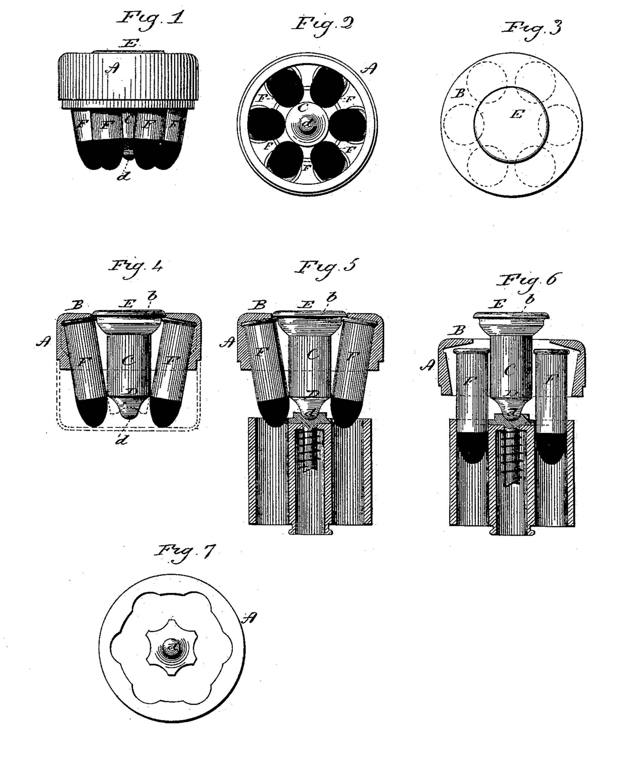
Figure 1, a side view of the pack complete; Fig. 2, a front end view; Fig. 3, a rear end view; Fig. 4, a vertical section showing the plug and two opposite cartridges in side view; Fig. 5, the same section as set over a cylinder of a revolver preparatory to loading; Fig. 6, the same section showing the cartridges as started into the cylinder and the plug as being ejected; Fig. 7, a modification in the shape of the plug and ring.
This invention relates to the construction of a device to hold cartridges in number and position corresponding to the chambers of the cylinder of a revolver, and so that cartridges arranged in such device may be together transferred to the respective chambers of the cylinder, instead of inserting the cartridges individually into the chambers of the cylinder, the object being a simple and effective device to hold the cartridges as a pack, yet so cheap in its construction that reason able economy will admit of its being thrown away after the cartridges have been removed; and the invention consists in a ring with an internal flange at one end, the internal diameter at the flange larger than the diameter at the opposite side, and with an annular groove upon the inside adjacent to the flange corresponding to the rims of the cartridges, combined with a plug adapted to be introduced through the opening in the flange, and of a length corresponding substantially to the length of the cartridges, the outer end of the plug constructed with an annular shoulder distant from the annular groove in the ring equal to the diameter of the heads of cartridges to be placed therein, and so that cartridges set within the ring, with the flanges in the groove thereof, and the plug introduced, its inner end will bear against the cartridges near the points, and the shoulder at its opposite end will bear against the rims of the cartridges, and so that the plug being forced out ward will leave the cartridges free for removal from the ring, as more fully herein after described.
A represents the ring, which is constructed with an inwardly-projecting flange, B, at one end, the internal diameter of the ring opposite the flange being preferably at least as great as the distance across the heads of two opposite cartridges when in the cylinder. The inside of the ring at the flange is of larger diameter than at the opposite side, and at the flange the ring is constructed with an internal annular groove, a, corresponding in shape substantially to the shape of the rims of the cartridges, and so that the cartridges set into the ring, with their rims in the groove, will take a bearing against the inside of the ring at the opposite end and stand in an inclined position, their points converging, as seen in Fig. 4.
C represents the plug, which is adapted to set through the opening in the flange B. Its inner end, as at D, is of a diameter corresponding to the space between the cartridges, and so as to take a bearing upon the inner side of the cartridges. The outer end of the plug forms a head, E, and is constructed with a shoulder, b, the diameter of which is less than the diameter of the annular groove a by substantially twice the diameter of the head of a cartridge, and so that when the plug is forced in between the cartridges its point end will take a bearing upon the inner side of the several cartridges, and the shoulder b will rest against the rims at the head end of the cartridges, and so as to hold the cartridges, ring, and plug in firm engagement with each other.
The size and arrangement of the pack are such that the points of the cartridges are in the range of the chambers in the cylinder, and so that the pack set over the chambers in the cylinder the points of the cartridges will be directed into the respective chambers, as seen in Fig. 5. Then the ring is forced toward the cylinder, and the extractor strikes the end of the plug and forces it outward, as seen in Fig. 6, which liberates the cartridges. Then the cartridges are free to come into line with the chambers and will freely drop therein. This done, the ring and its plug may be thrown away or retained for a new pack, if desired.
The inner end of the plug is constructed of a shape corresponding to the center of the rear end of the cylinder—that is, the extractor, ratchet, or whatever may be upon that center—and so as to locate the pack centrally on the cylinder. In case the center of the cylinder is a recess a corresponding projection, d, is formed on the inner end of the plug, as seen in Fig. 4. In case it is a projecting center then a corresponding recess will be formed in the plug, as indicated in broken lines, Fig. 4.
Preferably the diameter of the plug at its inner end should be no larger than the space between the two opposite heads of cartridges as they are arranged in the cylinder; but the diameter or sizes of the parts are immaterial, it only being essential that the construction be such that the points of the cartridges will come within the range of the several chambers in the cylinder and so as to enter the respective chambers when the pack is set over the cylinder.
The ring and the plug may be made from wood, so as to be of the cheapest possible construction, yet serviceable for the purpose indicated, and the ring may be provided with a drawn-up metal (or other material) cover, as indicated in broken lines, Fig. 4, so that the pack may be completely closed.
These packs are prepared in advance, so that when all the cartridges of a cylinder have been discharged they may be removed and at once replaced by fresh cartridges from the pack, as before described.
The body of the plug may be fluted, as indicated in Fig. 7, if desired, the flutes corresponding to the respective cartridges, and the ring may be fluted corresponding to the proper position of the respective cartridges, as also seen in Fig. 7, so that the cartridges will be positively located equidistant from each other. The ring and plug, one or both, may be made from metal, if desirable.
While I prefer that the plug should be ejected or thrown outward by its contact with the cylinder as the ring is forced toward the cylinder, the plug may be withdrawn by hand after the cartridges are entered.
The reduction in internal diameter of the ring from the flange toward the Opposite end may be made by shaping the ring gradually tapering upon the inside, as seen in Fig. 4; or the less diameter may be produced by an inwardly-turned flange, as indicated in broken lines, Fig. 4, it only being essential that the internal diameter of the ring opposite the flange shall be less than that at the flange, so as to bring the cartridges into the converging position, as shown and described.
So long as the plug remains in its position the cartridges are wedged into the ring and the pack will remain intact, but instantly upon the removal of the plug the cartridges are free.
The packs may be made up complete—that is, with the cartridges in place as articles of manufacture.
I claim—
1. In a cartridge-pack, a ring constructed with an internal flange at one end and with an annular groove upon the inside, adjacent to the flange, the diameter of the ring contracted toward the opposite end, combined with a plug adapted to be inserted from the flange end of the ring, the head end of the plug constructed with an annular shoulder adapted to bear against the inner edge of the cartridge-heads as they rest in the groove on the ring, and the plug near its inner end adapted to bear against the inner side of the cartridges near the points, substantially as described.
2. In a cartridge-pack, a ring constructed with an internal flange at one end and with an annular groove, upon the inside adjacent to the flange, the diameter of the ring contracted toward the opposite end, combined with a plug adapted to be inserted from the flange end of the ring, the head end of the plug constructed with an annular shoulder adapted to bear against the inner edge of the cartridge-heads as they rest in the groove of the ring, the plug near its inner end adapted to bear against the inner side of the cartridges near the points, and the inner end of the plug constructed corresponding to the center at the rear end of the cylinder, and so that the said rear center of the cylinder serves as a guide in the arrangement of the pack upon the cylinder, substantially as described.
CARL J. EHBETS.
Witnesses:
F. F. KNOUS,
EDWD. J. MURPHY.