
US 402423
UNITED STATES PATENT OFFICE.
CARL J. EHBETS, OF HARTFORD, CONNECTICUT, ASSIGNOR TO THE COLTS PATENT FIRE-ARMS MANUFACTURING COMPANY, OF SAME PLACE.
LOCK FOR FIRE-ARMS.
SPECIFICATION forming part of Letters Patent No. 402,423, dated April 30, 1889.
Application filed January 14, 1889, Serial No. 296,323. (No model.)
To all, whom it may concern:
Be it known that I, CARL J. EHBETS, of Hartford, in the county of Hartford and State of Connecticut, have invented a new Improvement in Locks for Fire-Arms; and I do hereby declare the following, when taken in connection. With accompanying drawings and the letters of reference marked thereon, to be a full, clear, and exact description of the same, which said drawings constitute part of this Specification, and represent, in—
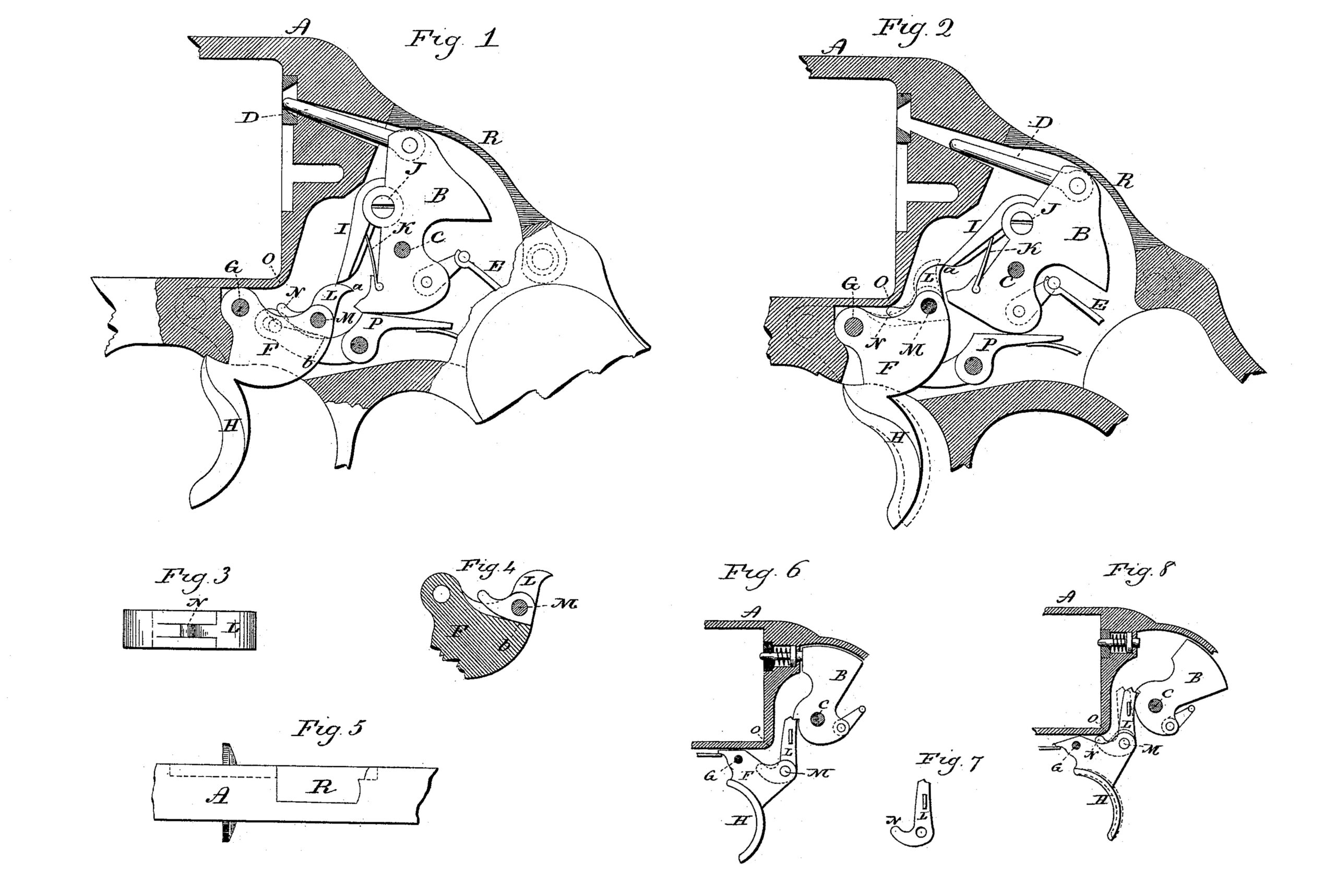
Figure 1, a sectional view of a revolver, showing side view of the lock mechanism in the normal position; Fig. 2, the same parts with the hammer thrown to the full-cock position; Fig. 3, a top view of the trigger, showing the dog as hinged therein; Fig. 4, a vertical section of the trigger, showing side view of the dog; Fig. 5, a top view of the frame on a reduced scale; Fig. 6, a sectional view of a revolver, showing side view of the mechanism in a modified form, the parts in the normal position; Fig. 7, a side view of the modified dog detached; Fig. 8, the parts the same as Fig. 6, but in the position of full-cock.
This invention relates to an improvement in locks for fire-arms, specially adapted to revolvers, and in which connection the invention is illustrated; and it relates particularly to that class which are made self-cocking by the pull of the trigger—that is, so that the pull upon the trigger will bring the hammer to full-cock position, and then a further pull of the trigger will release the hammer for discharge—it being specially adapted for concealed hammers, the object being to mechanically indicate when the hammer has reached the full-cocked position, so that the operator may, if he chooses, hold the hammer in that position before continuing the pull of the trigger to produce discharge; and the invention consists in the combination of elements hereinafter described, and particularly recited in the claims.
A represents the frame of a revolver; B, the hammer, hung upon a pivot, C. Under this arrangement the hammer is inclosed entirely within the frame, and is provided with a firing-pin, D, hinged to the hammer, so as to move with it, as indicated in Figs. 1 and 2.
E represents the mainspring, which is hung to the hammer in rear of its pivot in the usual manner.
F represents the trigger, which is hung upon a pivot, G, forward of the hammer, and is constructed with the usual finger-piece, H.
To the hammer, and forward and above its pivot, a strut, I, is hinged, as at J. The strut, extending downward, is provided with a spring, K, the tendency of which is to force the lower end or nose of the strut I forward over the trigger. Upon the upper side of the trigger, and in rear of its pivot, a dog, L, is hung, as at M. The nose a of the dog normally stands below the strut I, and so that the strut in its forward position stands directly over the dog, as seen in Fig. 1. The under side of the dog, at its rear, is constructed to take a bearing upon the trigger, as at b, and so that the dog is prevented from turning rearward out of its normal position; hence when the trigger is pulled, as from the position in Fig. 1 to that seen in Fig. 2, the dog bears against the end of the strut and forces the hammer to its cocked position, as seen in Fig. 2.
From the forward side of the dog a tail, N, extends, and in the frame is a bearing point or shoulder, O, in the path of the tail of the dog as the trigger is pulled to bring the hammer to its cocked position, and so that as the hammer reaches the cocked position, as seen in Fig. 2, the tail N of the dog will strike this shoulder or bearing O in the frame. Then a continued pull of the trigger will cause the trigger to operate the dog as a level, the stationary bearing O being a fulcrum, and so that the nose of the dog will be thrown forward, as indicated in broken lines, Fig. 2, and permit the strut to escape therefrom and the hammer to be thrown forward. Then as the trigger is released the dog descends with it, the strut yielding for the descent of the dog until it has passed below the strut. Then the strut will be thrown forward over the dog to the normal position, as seen in Fig. 1, ready for the next pull.
The leverage of the trigger upon the strut in the pull from the normal position to the full-cocked position is the greatest; but as soon as the tail of the dog comes upon the stationary bearing O in the frame then the leverage is reduced sufficiently to indicate to the finger pulling the trigger that an interruption has occurred, and this interruption indicates the full-cock position of the hammer, so that the operator may readily pull the trigger until this interruption occurs, and there hold, if desirable, until such time as aim may be taken or the completed pull is required, or, if not required, that the hammer may be let down to its rebound position without striking the primer of the cartridge, for if the trigger and the hammer are thus allowed to descend before the point of the strut escapes from the nose L of the trigger dog the position of the rebound-lever P is such that it positively prevents the point of the firing-pin from reaching the primer. This rebound-lever P is a well-known device for this purpose, and as it does not materially qualify the present invention a full description of its operation herein is unnecessary.
It will be understood that the length of the tail of the trigger-dog may be made shorter or longer, correspondingly increasing or reducing the power required for the final pull of the trigger.
The dog is preferably hung in a recess in the upper side of the trigger, as indicated in Figs. 1 and 4, so that the dog presents a broad surface to operate against the strut. I have omitted the hand or pawl for imparting rotation to the cylinder, as its presence would somewhat obscure the illustration. The hammer-opening through the top of the frame is closed by a flange, R, which extends from the side plate on the case, as seen in Fig. 5.
I have represented the strut by which the movement of the trigger is imparted to the hammer as hinged to the hammer; but the dog may be made to operate directly upon the hammer without the interposition of the strut, as seen in Figs. 6, 7, and 8, Fig. 6 representing the parts in the normal position and Fig. 7 as in the cocked position when the tail of the dog has come to its bearing, broken lines indicating the completed pull for discharge.
While representing the invention as applied to a concealed hammer, it will be evident that it may be employed to the same advantage with an exposed hammer, it being immaterial to the invention whether the hammer be concealed or exposed. The illustration of the invention as applied to locks for revolvers will be sufficient to enable others skilled in the art to apply the mechanism to locks for other fire-arms.
I claim—
1. In a fire-arm, the combination of a hammer hung upon a pivot in a frame, a trigger hung forward of the hammer, a dog hung upon the trigger in rear of its pivot, the nose of the dog extending upward, a shoulder on the trigger to arrest the rear movement of the dog, a tail extending forward from the dog, the nose of the dog adapted to engage the hammer on the pull of the trigger, and a stationary bearing in the frame in the path of the tail of the dog, and against which bearing the tail of the dog will strike as the hammer is brought to the full-cocked position and before its release, substantially as described.
2. In a fire-arm, the combination of the hammer B, hung upon a pivot in the frame, a strut, I, hinged to the hammer above and for ward of its pivot, the said strut extending downward and provided with a spring the tendency of which is to turn the strut forward, the trigger F, hung in the frame for ward of the hammer, the dog L, hung upon the trigger in rear of its pivot, the trigger constructed with a bearing, b, against which the dog rests in its normal position, the dog extending upward, its nose adapted to engage the lower end of said strut and provided with a forwardly-projecting tail, N, and a stationary bearing, O, in the frame in the path of the tail of the dog, substantially as and for the purpose described.
CARL J. EHBETS.
Witnesses:
EDWD. J. MURPHY,
FRANKLIN F. KROUS.