
US 185881
UNITED STATES PATENT OFFICE.
ANDREW E. WHITMORE, OF ILION, NEW YORK.
IMPROVEMENT IN REVOLVING FIRE-ARMS.
Specification forming parts of Letters Patent No. 185,881, dated January 2, 1877; application filed October 11, 1876.
To all whom it may concern:
Be it known that I, ANDREW E. WHITMORE, of Ilion, in the county of Herkimer and State of New York, have invented certain Improvements in Revolving Fire-Arms, of which the following is a full, clear, and exact description, reference being had to the accompanying drawings, making part of this specification, in which–
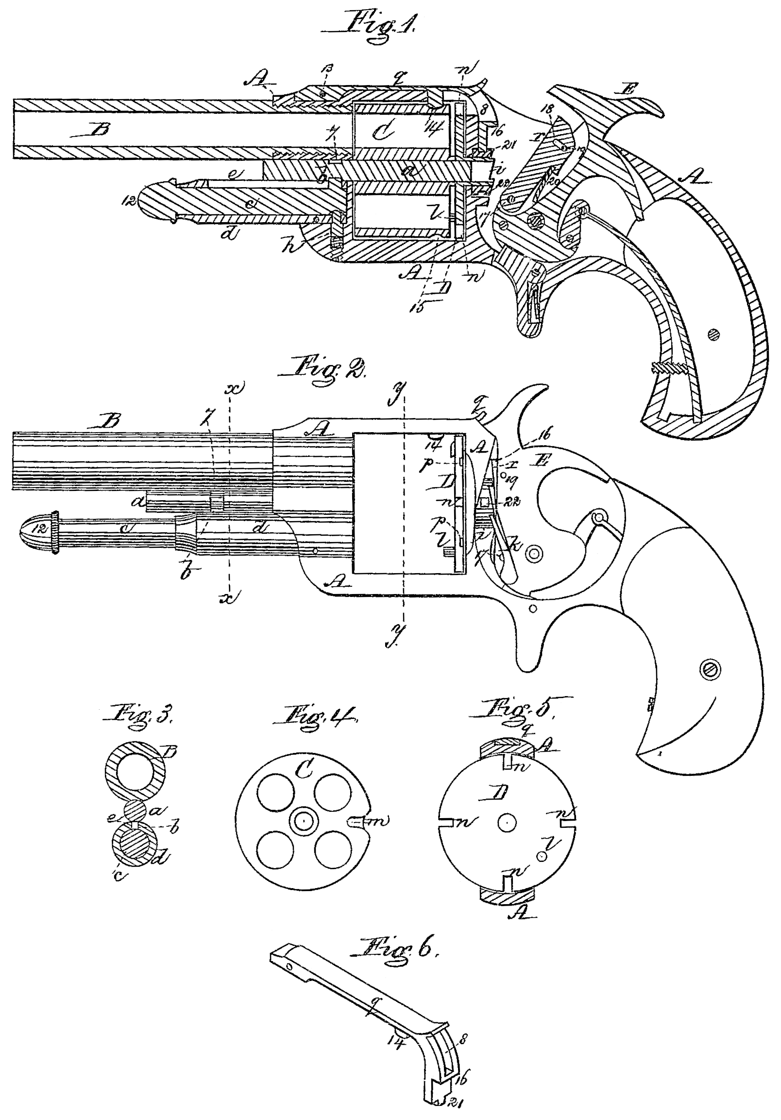
Figure 1 is a longitudinal section through the center of a revolver constructed in accordance with my invention, the cylinder being in place. Fig. 2 is a side elevation of the same, the cylinder and lock-plate being removed. Fig. 3 is a transverse section on the line x x of Fig. 2. Fig. 4 is an elevation of the rear end of the cylinder. Fig. 5 is a transverse section on the line y y of Fig. 2. Fig. 6 is a perspective view of the stop-lever detached.
My invention consists in a spring stop-lever of peculiar construction for locking the cylinder in its firing position, in combination with a mechanism for raising it and releasing the cylinder, whereby I am enabled to employ a stiffer spring than heretofore in connection with the stop-lever, and thus render its hold upon the cylinder more secure.
To enable others skilled in the art to understand and use my invention, I will proceed to describe the manner in which I have carried out.
In the said drawings, A represents the frame of a revolver-pistol, to which is screwed the barrel B. C is the chambered cylinder, which is fitted within a rectangular opening in the frame, and is supported upon a long pin, a, which passes centrally through it. This pin a slides through the front of the frame, and, after passing through the cylinder, projects out beyond its rear end and enters an opening at the center of a recoil-plate, D, to be hereafter described.
The pin a is provided with an annular groove, 7, into which fits a projection, b extending up from the extractor-pin c, which slides in a tube or guide, d, secured to and projecting from the front of the frame A beneath the barrel B, the pin b being traversed in a slot, e, in the top of the tube d, and, by thus connecting the extractor-pin with the axial pin a, the latter can be entirely withdrawn from the cylinder by taking hold of the head 12 of the extractor-pin c, and drawing it longitudinally out of its guide-tube d, as seen in Fig. 2. The cylinder is then free to be removed from the frame, after which the empty shells can be forced out by applying the cylinder to the extractor-pin in the usual manner.
The extractor-pin, when pushed into its guide-tube d, is held securely, so as to prevent the accidental dropping out of the cylinder, by a spring friction-catch, h, the resistance of which can be readily overcome by pulling on the head of the extractor-pin, and as there are no springs connected with the axial and extractor pins the construction is greatly simplified, and the liability of getting out of order, incident to this class of revolvers, (previously referred to,) is materially diminished.
By providing the axial pin a with the annular groove, 8, for the projection b to fit into, the pin is free to revolve with the cylinder, in case it should adhere thereto.
The recoil-plate D consists of a circular disk, provided at its rear with a central ratchet-hub, i, which fits snugly within and passes through a circular aperture in the frame A. With this ratchet-hub engages a pawl, k, pivoted to the hammer E, the movement of which effects the revolution of the recoil-plate in a well-known manner, the rotation of the recoil-plate being imparted to the cylinder by a pin, l, which enters a recess, m, Fig. 4, in the cylinder. This recoil-plate is provided at its periphery with a series of notches, n, corresponding in number to those of the chambers in the cylinder, the notches allowing the pointed end of the hammer to pass into contact with the flanged ends of the cartridges, the portion of the recoil-plate between the notches serving as a guard to prevent the hammer from striking a cartridge when it is not directly in line with the barrel. On the rear face of the recoil-plate, intermediate between the notches n, are a corresponding number of recesses, p, with which the point of the hammer engages, to hold the cylinder immovably out of the firing position, thus preventing any liability of the accidental discharge of the pistol. The recoil-plate remains permanently attached to the frame A after the removal of the cylinder C, and by the use of this plate the friction heretofore produced between the flanged ends of the cartridges and a stationary recoil-plate is avoided. q is a stop-lever, made of spring metal, and let into the top of the frame A so as to lie flush there with. This lever is attached at one end to the frame at 13, and is provided on its underside with a stop or projection, 14, which is intended to catch successively into the recesses 15, formed in the outer surface of the cylinder C, for the purpose of holding it properly in its firing position. The rear end of the lever g is provided with a slot, 8, for the passage of the point of the hammer, and is lifted to withdraw the stop 14 out of a recess, 15, and release the cylinder, to allow of its being rotated to bring the next chamber in line with the barrel in the following manner: The free end of the lever q is bent down, as seen in Figs. 1 and 6, and is provided with a shoulder, 16, under which, when the hammer is down, projects the upper end of a lever, r, which is pivoted at its lower end to the hammer at 17, and fits into a long recess formed therein for its reception. The upper end of this lever r is provided with a slot, 18, through which passes a pin, 19, which limits its forward motion, a light spring, 20, being placed behind it, as seen in Fig. 1.
As the hammer is drawn back in the act of cocking, the lever r is raised, causing its upper front corner to bear against the shoulder 16 and lift the lever q to withdraw its stop 14 from one of the recesses 15, the spring 20 forcing the lever r forward and keeping it under and in contact with the shoulder 16 until the pin 19 comes in contact with the rear end of the slot 18, when the upper corner of the lever is withdrawn from under the shoulder 16.
A projection, 21, on the lower end of rear portion of the lever q, then rests upon the outer surface of the ratchet-hub i until, as the latter revolves it drops into one of a series of recesses, 22, therein, leaving the lever free to spring down and lock the cylinder in its firing position, the recesses 22 in the hub i being so arranged with respect to the recesses 15 of the cylinder, that one of the former, 22, will arrive beneath the projection 21 at the same instant that one of the recesses 15 is brought under the stop 14 of the lever q. On the descent of the hammer the front of the upper end of the lever r strikes the lever q, causing the lever r to be forced back into its recess within the hammer against the resistance of the spring 20, and as soon as the upper corner of the lever r is brought below the shoulder 16, the spring 20 instantly throws it forward thereunder into the position seen in Fig. 2, ready to again lift the lever q, as before described. The aforesaid lifting device is simple and effective, and by its use a stiffer spring may be employed in connection with the stop-lever than heretofore, thus causing it to hold the cylinder more securely in its firing position than heretofore. By the employment of the projection 21 in connection with the recesses 22 in the ratchet-hub i, the stop 14 is held up out of contact with the surface of the cylinder until one of the recesses 15 is brought directly beneath it, and I am thus enabled to avoid the friction upon and consequent marring of the outer surface of the cylinder, as would occur if the stop 14 rested constantly on its surface.
What I claim as my invention, and desire to secure by Letters Patent, is–
The lifting-lever r, provided with a spring, 20, and pivoted to the hammer, in combination with the stop-lever q, having a shoulder, 16, operating substantially as and for the purpose described.
Witness my hand this 5th day of October, A. D. 1876
ANDREW E. WHITMORE,
In presence of –
P .E. TESCHEMACHER,
W. J. CAMBRIDGE.