
US 158957
UNITED STATES PATENT OFFICE.
WILLIAM MASON, OF HARTFORD, CONNECTICUT, ASSIGNOR TO COLT’S PATENT FIRE-ARMS MANUFACTURING COMPANY, OF SAME PLACE.
IMPROVEMENT IN REVOLVING FIRE-ARMS.
Specification forming part of Letters Patent No. 158,957, dated January 19, 1875; application filed December 8, 1874.
CASE B.
To all whom it may concern:
Be it known that I, WM. MASON, of Hartford, in the county of Hartford and State of Connecticut, have invented a new Revolver; and I do hereby declare the following, when taken in connection with the accompanying drawings, and the letters of reference marked thereon, to be a full, clear, and exact description of the same, and which said drawings constitute part of this specification, and represent, in–
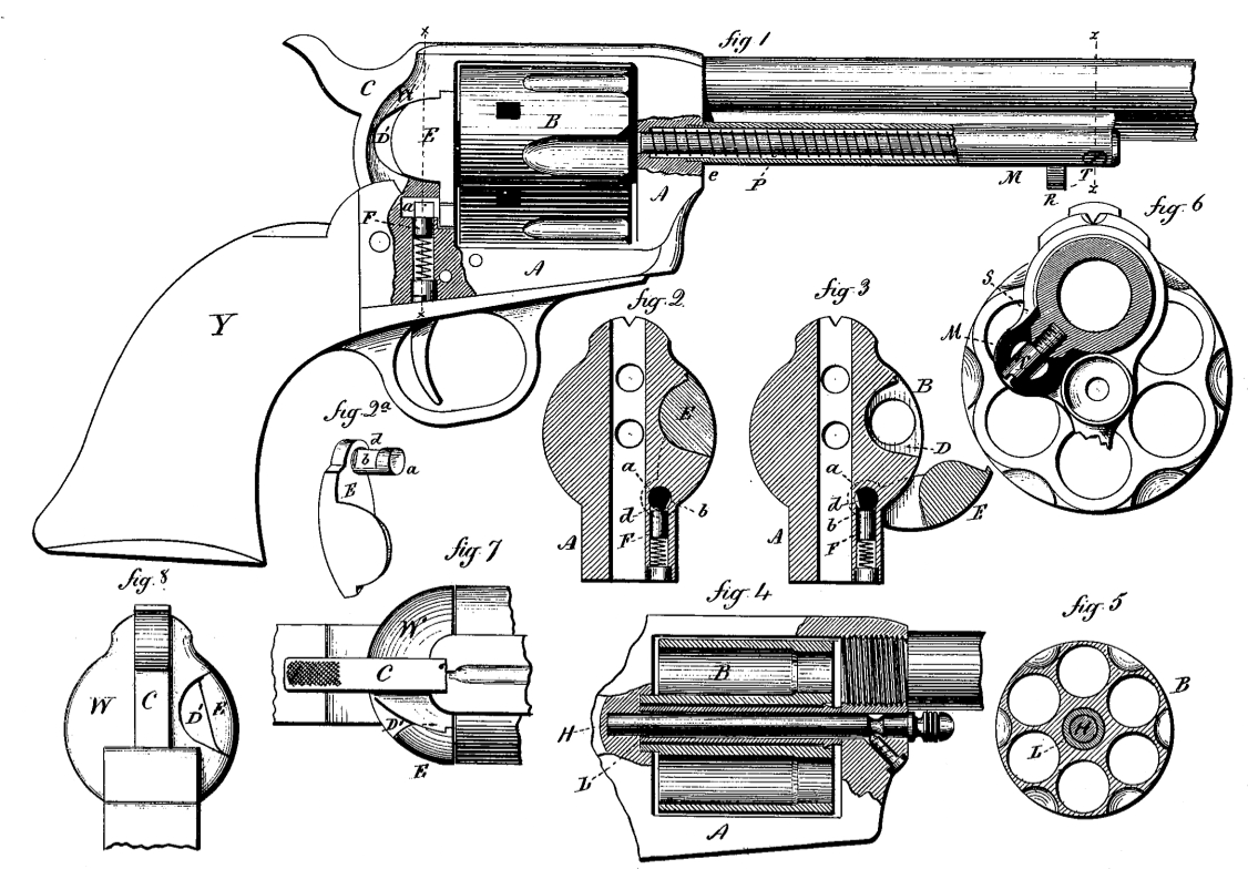
Figure 1, sectional side view; Figs. 2 and 3, vertical sections through the frame on line a ac, showing the gate closed and open; Fig. 4, longitudinal central section through the cylinder; Fig. 5, transverse section through the cylinder; Fig. 6, transverse section on line x x, looking to the rear, enlarged; Fig. 7, top or plan view of the rear of the frame; and in Fig. 8, rear view of the same.
This invention relates to an improvement in that class of fire-arms in which is employed a many-chambered revolving cylinder, to present successively each chamber to the rear open end of a single barrel, and commonly called revolvers, the object of the improvements being to facilitate the manufacture of the arm, as well as the manipulation of some of its parts; and the invention consists, first, in constructing the gate-trunnion flat upon two sides at nearly right angles to each other, and combining therewith a spring to bear upon the said trunnion, to force and hold the gate in either the open or closed position, according as either of the said two sides is presented to the influence of said spring; second, in securing the ejector-tube by means of a boss on the barrel, and screw transversely through the tube into said boss and a recess in the frame, into which the rear end of the tube extends; third, in constructing the rear end of the frame in semi-spherical form, the gate forming a part of the said semi-spherical rear end–all as more fully hereinafter described.
A is the frame, in which is arranged the cylinder B and hammer C, with their operative mechanism, in substantially the usual manner. In order to introduce the cartridges and remove the shells, a cavity, D, is formed in the rear end of the frame, in line with the chambers of the cylinder, so that in revolving the cylinder, the chambers successively pass the cavity D. This cavity is closed by a gate, E, hung to the frame by a trunnion, a, parallel with the axis of the cylinder, so that the gate may be turned away, as in Fig. 3, to expose the corresponding chamber in the cylinder, or returned to close the same, as in Fig. 2. On two sides, at nearly right angles to each other, a portion of the trunnion is cut away, as seen in Fig. 2, forming two recesses, b d, in the trunnion. In the frame beneath the trunnion a spring-follower, F, is arranged, the tendency of the spring being to press the follower against the trunnion, and in such relative position to the trunnion that when the gate is closed the angle between the two flat surfaces on the trunnion will be outside the vertical axial plane of the trunnion, as seen in Fig. 2. Thus, bearing upon the angle of the trunnion, the spring-follower F tends to close the gate as the said angle passes the axial plane, and to hold the gate in its closed position.
In opening the gate, the trunnion turns and depresses the follower, until the said angle of the trunnion passes to the opposite or inside of said axial plane; then the follower forces the gate open, as seen in Fig. 3, and holds it in that position. Therefore, while the follower F will yield for the opening and closing of the gate, it will force it to and hold it in either extreme position.
The length of the recesses cut in the trunnion in forming the said flat surfaces is the same as the diameter or width of the follower F, or constructed so that the inner shoulder of the recesses will come close in rear of the follower; therefore, when the gate is in its place the follower F will set into the said recesses, and thus hold the gate in its bearing without other security.
As there is, practically, very little strain upon the center-pin H, it may be of as small diameter in large as small arms, and such small diameter is desirable in order to keep the cylinder of small diameter, and yet permit the projecting end of the center-pin to clear the barrel, so that the pin may be with drawn toward the muzzle; but in the manufacture of cylinders for the larger class of pistols an opening through the cylinder no larger than that required for the pin is too small for practical purposes, as a mandrel or arbor of that diameter would be too weak for practical use. To overcome this difficulty in the manufacture and still preserve the desirable small center-pin, the cylinder is center bored of sufficient diameter for the requirements of manufacture; and into this center bore a sleeve, L, is fitted, as seen in Figs. 4 and 5, the internal diameter of the sleeve cor responding to the diameter of the center-pin, the sleeve loose both on the pin and in the cylinder, and the pin loose in the frame, so that the cylinder will turn freely on the sleeve, and the sleeve as freely on the pin or the pin in the frame.
This construction has an additional advantage over a construction without the sleeve– that is, as there are three bearings, upon either of which the cylinder may revolve, there is less liability of the cylinder sticking than in case of a single bearing.
M is the ejector-tube, arranged longitudinally on the barrel, in line with the gate E. Within this tube is the ejector-rod P, which is moved through the cylinder, to eject the shell or cartridge, by means of a finger-piece, R, and returned to the tube by a spiral spring. (Shown in Fig. 1.) To attach this tube and not weaken the barrel, a boss, S, is formed upon the barrel and a corresponding cavity in the ejector tube, as seen in Fig. 6. The rear end of the tube is set into a recess in the frame, as at e, and the cavity at the other end of the tube set over the boss S. Then a screw, T, transversely through the tube into said boss secures the tube to the arm, and the barrel is not weakened by tapping for the screw, and any strain or blow upon the tube will come not upon the screw, but upon the boss directly, which is capable of resisting a much greater strain than the screw.
The force of the recoil in the larger class of revolvers is very great, and that part of the frame in rear of the cylinder must be proportionately strong. This rear part is necessarily broken by the gate, and in the usual construction this has presented an abrupt change in the surface, making it liable to catch in drawing from the belt or holster. In order to give this required strength and avoid such abrupt changes in the surface of the frame, and at the same time preserve the light appearance of the arm, that portion, W, of the frame in rear of the cylinder and above the stock Y is made of spherical form, of the same diameter as the cylinder, as seen in Figs. 1, 7, 8, the gate E forming a part of the spherical surface, a portion of the rear of the gate cut away to leave a recess, D’. As a convenience in opening the gate, the hammer is hung so as to work in a vertical recess in this spherical end. This construction, while affording very great strength to that part of the arm, takes away their heavy appearance of the usual construction, and avoids the difficulties attending the employment of the gate before mentioned.
I claim as my invention and desire to secure by Letters Patent–
1. The gate E of a revolver, having its trunnion a constructed with flat recesses b d, and combined with the spring-follower F, substantially as described.
2. In a revolving fire-arm, the boss S on the barrel, and the recess e in the frame, combined with the ejector-tube, constructed to enter said recess e, and set over the boss S, as a means for securing said tube to the arm, substantially as specified.
3. In a revolver provided with a gate, the rear or recoil portion of the frame, constructed of spherical form, the gate E forming a part of said spherical portion, substantially as described.
WILLIAM MASON.
Witnesses:
C. B. RICHARDS,
ROBT. C. THOMSON.