
US 132357
UNITED STATES PATENT OFFICE.
JOSHUA DAVIS, OF LIMESTONEVILLE, PENNSYLVANIA.
IMPROVEMENT IN GAS-CHECKS FOR REVOLVING FIRE-ARMS.
Specification forming part of Letters Patent No. 132,357, dated October 22, 1872.
To all whom it may concern:
Be it known that I, JOSHUA DAVIS, of Limestoneville, in the county of Montour and State of Pennsylvania, have invented certain Improvements in Revolving Fire-Arms, of which the following is a description:
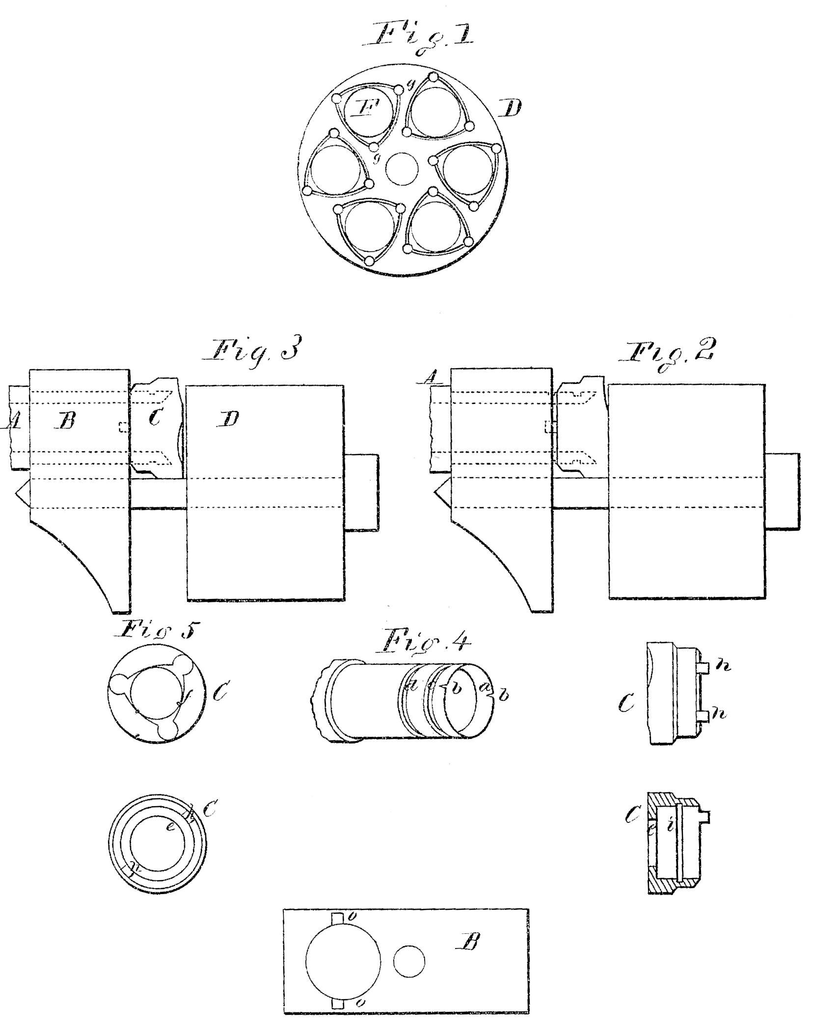
In the accompanying drawing, Figure 1 is a front-end view of the cylinder of my improved fire-arm; Fig. 2 is a side view of the part of a fire-arm embodying my invention, showing the position of parts at the moment of discharge; Fig. 3 is also a side view, showing the position of parts previous to the dis charge; Fig. 4 is a perspective view of the rear end of the barrel; Fig. 5 is a rear-end view of the frame in front of the cylinder; and Figs. 6, 7, 8, and 9 represent details.
My invention has relation to revolving firearms; and it consists, first, in the construction and novel arrangement of the barrel, socket, frame, and cylinder, as hereinafter described, whereby the escape of gases between the rear end of the barrel and a chamber of the cylinder when the fire-arm is discharged is prevented, and the velocity of the ball consequently increased; second, in the construction and novel arrangement of the barrel, cylinder, socket, and frame whereby the socket, after being moved by the discharge of the fire-arm, is automatically replaced and the cylinder allowed to be turned without the friction otherwise consequent.
Referring to the accompanying drawing, A represents the rear end of the barrel reamed out, as shown at a, Fig. 4, to a thin edge at the exterior surface to render it elastic and allow it to press tightly against the interior surface of the socket C, when the latter is moved by the force of the gases. b b represent slits in the part a to allow the latter to expand. c d represent grooves cut around the surface of the barrel, as shown. The purpose of the groove d is to prevent the banking of dirt or residuum, the same being fractured as it accumulates by the concussion of the forward end of the socket C, when the same moves forward from the position shown in Fig. 2 to that shown in Fig. 1. The groove c is designed, in connection with the groove i in the interior surface of the socket C, to prevent the rear end and exterior surface of the barrel from adhering to the interior surface of the socket. As shown in Fig. 3, the groove i is forward of the groove c, this being the position before the discharge of the arm. Thus the exterior surface of the rear end of the barrel touches the interior surface of the socket the distance only from the groove d to the edge of the concave part a less the width of the two grooves c and i, but at the moment of discharge, when the socket moves backward, as shown in Fig. 3, the grooves i c are made to coincide, increasing the extent of contact surface of the barrel and socket the width of one groove, thereby making a tighter joint. The socket C is provided with a flange, e, against which the gases press to move the socket back against the face of the cylinder D. The socket is also provided with lateral projections or studs h h, fitting recesses o in the surface of the frame B and serving to prevent the socket from turning as it moves forward and backward. The diameter of the interior edge of the flange e or rear end of the socket C may be made the same as the caliber of the barrel and cylinder chambers, but I prefer to have the diameter of said flange about one-fiftieth of an inch larger. Between the inner edge of said flange and the irregular lines f lies the surface of the socket, which, by pressing against the surface of the cylinder, prevents the escape of gases at that point, and also covers the grooves x x x and holes g g g in the surface of the cylinder at the moment of discharge. Outside the irregular lines f the surface of the socket is beveled to prevent the residuum from adhering to it. The holes shown at g g g are designed to receive gas sufficient to move the socket forward after the discharge. These holes are far enough away from each respective chamber to prevent their impairing the strength of the cylinder. The grooves a a a are for the purpose of conducting the gas to the holes g g g. It is obvious that the holes g g may be made in the socket instead of the cylinder.
Now, supposing the fire-arm having the herein-described improvements be discharged properly and in the usual way, the result is a sudden conversion of the charge into gases. These gases, after the ball has passed the rear end of the barrel, expand the concave part a while the slits b are choked or closed by the dirt and residuum getting between the contiguous surfaces of the socket and barrel. The pressure of the gases also upon the flange e forces the socket back against the face of the cylinder, preventing the gases from escaping at that point and closing the holes g and grooves x x, the same having been filled with gas. As Soon as the ball leaves the muzzle of the barrel the pressure of the gas ceases, except that within the holes which now moves the socket back to its original position.
What I claim as new, and desire to secure by Letters Patent, is–
1. The cylinder D having the holes g and grooves x, in combination with the sliding socket C and barrel A, substantially as specified.
2. The barrel A having its rear end reamed and slit, as shown at a b, in combination with the movable socket C, substantially as described.
3. The barrel A having the grooves c d in combination with the movable socket C having the internal groove i, substantially as described.
4. The combination of the barrel A, movable socket C, frame B, and cylinder D, substantially as described.
JOSHUA DAVIS.
Witnesses:
HENRY KAISER,
EDM. E. BROWN.