
US 42688
UNITED STATES PATENT OFFICE.
HENRY REYNOLDS, OF SPIRINGIFIELD, MASSACHUSETTS.
IMPROVEMENT IN REVOLVING FIRE-ARMS.
Specification forming part of Letters Patent No. 42,688, dated May 10, 1864.
To all whom it may concern:
Be it known that I, Henry Reynolds, of Springfield, in the county of Hampden and State of Massachusetts, have invented a new and useful Improvement in Revolving Fire-Arms; and I do hereby declare that the following is a full, clear, and exact description of the same, reference being had to the accompanying drawings, forming part of this specification, in which—
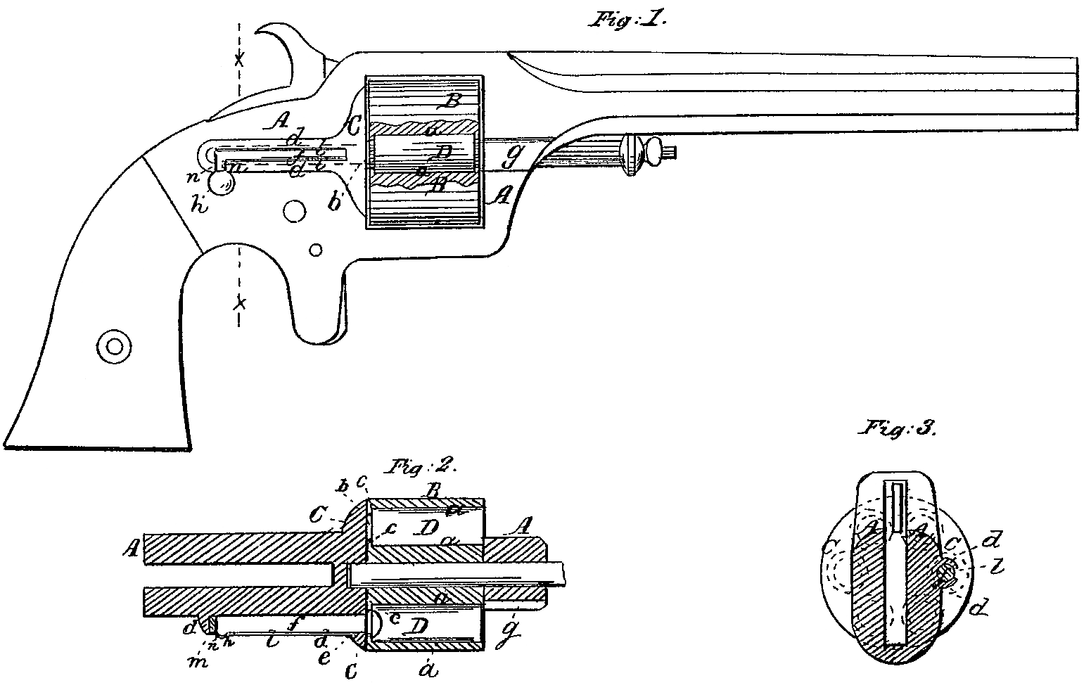
Figure 1 is a side view of a pistol with my improvement, representing the cylinder partly in section. Fig. 2 is a horizontal section of the same, taken through the axis of the cylinder. Fig. 3 is a transverse section of the same.
Similar letters of reference indicate corresponding parts in the several figures.
This improvement relates to revolving fire-arms for the use of fixed ammunition or other metallic cartridges, and its object is to provide for the expulsion of the discharged shells of such cartridges.
To enable others skilled in the art to make and use my invention, I will proceed to describe it with reference to the drawings.
A is the frame of the arm, of any suitable construction.
B is the revolving cylinder, having its chambers a a bored from the front end to within a suitable distance from the rear, for loading in front, and having a central opening, b, in the rear of each, through which the sliding pin, bolt, or piston f can enter for expelling the cartridge-shells in a forward direction, a sufficient shoulder, c, being left around the said opening to serve as a resting-place or bearing for the rear end of the cartridges D, which are inserted from the front of the cylinder.
On the right-hand side of the frame A, in rear of the recoil-shield C, there is a swell, d, of such form as to enable it to be bored longitudinally for the reception of the sliding plunger f, which is of a size to pass easily through the openings l in the chambers, and for the passage of which there is also provided in the recoil-shield a hole, e, Fig. 2. The plunger f is arranged parallel with the axis of the cylinder, and in such position that by the revolution of the cylinder the several chambers may be brought directly opposite to the said plunger. On the same side of the frame in front of the cylinder, there is a slight groove, g, to allow the cartridge-shells to pass out of the chambers in a forward direction, When they are severally brought opposite to the plunger f. In all other positions the chambers are either wholly or partly covered by the front portion of the frame or by the barrel, and the chambers never stop in this position in the operations of firing and preparing to repeat the fire; but when the hammer is at half-cock the cylinder is free to be turned by hand to bring the several chambers in turn to this position.
The plunger f has attached to its rear end a small knob or handle, h, which can be taken hold of by the thumb and finger to work the plunger back and forth, and a longitudinal slot, l, is provided in the swell d for the said handle to work in.
At the bottom of the slot l, close to its rear end, there is a notch, n, into which, when the plunger is drawn back clear of the cylinder, the handle h drops for the purpose of preventing it from being accidentally moved forward; and to make the handle secure in this notch there is a spring, m, Fig. 2, which may be composed of a small piece of vulcanized india-rubber, as represented, or of coiled steel wire inserted between the rear end of the bolt and the back of the bore of the swell d, which presses the handle hard against the front of the notch n.
When it is desired to expel the discharged cartridge-shells from the cylinder the hammer is brought to half-cock, and the handle h is taken hold of and raised up till it strikes the top of the slot l. The cylinder is then turned by hand to present the several chambers, one at a time, opposite the plunger, and on each one having been brought to this position the plunger is moved forward through its opening b far enough either to expel the cartridge-shell entirely from the said chamber or to make it protrude sufficiently through the front to enable it to be pulled out with the fingers. When the shell has been expelled or removed from this chamber the plunger is drawn back to allow the cylinder to turn to present the next chamber opposite to it.
The loading may be effected through the groove g while the hammer is at half-cock and the cylinder free to be turned to present the several chambers successively in the proper position.
I do not claim broadly the application of sliding bolts to fire-arms for the purpose of expelling the cartridge-shells; but
What I claim as my invention, and desire to secure by Letters Patent, is—
The arrangement of the pin f upon the stock A at the rear of the recoil-shield C, so as to pass through the said shield, all in the manner herein shown and described.
HENRY REYNOLDS.
Witnesses:
P. B. Tyler,
E. H. Plant.