
British 1785
A.D. 1864, 16th July. № 1785.
Breech-loading Fire-arms and Ordnance.
LETTERS PATENT to Andrew Wyley, of Barker Street, Aston Manor, in the County of Stafford, Geological Surveyor, for the Invention of “Improvements In Breech-Loading Fire-Arms, Including Revolvers And Ordnance.”
Sealed the 7th October 1864, and dated the 16th July 1864.
PROVISIONAL SPECIFICATION left by the said Andrew Wyley at the Office of the Commissioners of Patents, with his Petition, on the 16th July 1864.
I, Andrew Wyley, of Barker Street, Aston Manor, in the County of Stafford, Geological Surveyor, do hereby declare the nature of the said Invention for “Improvements “Improvements In In Breech-Loading Fire-Arms, Including Revolvers And Ordnance,” to be as follows:—
My improvements refer mainly to fire-arms in which the breech, or breech chamber is connected to the barrel by means of a screw having portions of the external and internal threads cut away, so that the one will slide longitudinally within the other, and then interlock by a partial turn.
I shall first describe a single gun constructed according to this Invention.
The rear of the barrel is formed or fitted with a breech case of the same shape as the breech case described in the Specification of a Patent granted to Andrew Wyley, and dated the 2nd of October 1861, (No. 2453,) and figured in Sheet I. of the Drawings attached to same, with the exception that it is much shorter, not extending further back than the screwed part, and has attached to its lower portion a lump of a depth equal to that of the wood of the stock. The breech chamber which for brevity I will henceforth call the breech, is also formed like that described and shewn in said Specification and Drawings, excepting that it is without the lever, and is firmly attached to the stock by means of a piece which takes the place of the ordinary break-off, and which may be called by that name. In this last the percussioning is placed. A back-work lock is used. The stock is divided in front of said break-off, and between the fore and rear parts a carrier or collar is placed, embracing that portion of the breech between the screw and break- off; it is furnished with a spindle at its lower part, travelling in a hole in the lump under the breech case parallel with the barrel’s axis. To open the breech the stock is turned one quarter round, by which the screw is disengaged; breech, collar, and spindle are then drawn back till the former is free of the breech case; they are then made to swivel to the right upon the collar spindle until the breech is so far clear of the stock that the cartridge can be introduced or withdrawn: the breech, is closed by reversing the above motions. I prefer as cartridge a pasteboard tube slightly turned in at the rear end, which is covered with any thin material permeable to the cap fire. The cartridge may be inserted a short way into the barrel, which is chambered out for that purpose, and the breech slid over its rear end; in this case the ball which projects from the cartridge may be mechanically fitting, or it may be placed in the breech chamber. To use loose powder a metal tube is inserted in the breech to form a permanent cartridge as it were. A spring stop is used to hold the breech in the locked position and in that of being withdrawn. A stop is also employed to act on the spindle and prevent its turning till it has been drawn out the requisite distance; by removing this stop the fore and rear parts of the fire-arm are separated for cleaning or packing. Instead of forming the breech in one piece with the break-off, I sometimes screw or otherwise fit the former into the latter, the percussioning being carried across the joint; thus central fire may be obtained, a steel breech hardened in oil, and tempered, may be conveniently used, and the carrier collar may be formed in one piece. I sometimes form the breech case of steel in one piece with a steel barrel, and harden and temper the former, occasionally including that portion of the barrel which is enlarged to receive the cartridge; for this purpose two heavy metal rings are used, fitting close to the barrel, one is placed on the barrel while being heated, and prevents the heat from extending up the barrel; the heat is got up as rapidly as possible, and the metal ring knocked off and replaced by a cold one.” In order still further to define the junction between the red hot and cooler portions of the barrel before it is immersed in the hardening fluid.
In the second mode of construction the lump under the breech case, collar, and spindle, may be dispensed with. Two straps are made to extend back- wards from the cheeks of the breech case carrying a couple of pins at their rear extremity made to project inwards in a line with each other. These pins work in grooves formed on opposite sides of the breech chamber, and permit of its being turned one quarter round so as to disengage the screw, and then withdrawn so far that it can tilt up out of the line of the barrel to receive the charge, oscillating on the above pins as centres, till it is stopped by the bottom of the breech case which is extended backwards beyond the cheeks. This construction is applicable to ordnance. The requisite motions are, in this case, given to the breech by a lever or handles at its rear end. In large guns holes are also made in which hand-spikes may be inserted. The lower part of the breech case forms a bed in which the breech slides when drawn back or pushed in. The position of the pins and length of the grooves are so regulated that when the breech is tilted up its rear overbalances its fore part, but when the charge is introduced the balance should be nearly even. I prefer to line the breech chamber with a tube of steel hardened in oil and brought to a low spring temper. The fore part of this tube projects and enters some way into the barrel or chase as in small arms.
In small fire-arms the breech chamber is moved by the stock to which it is attached, as in the first method of construction, I here for the most part make the breech case of circular outline, dispensing with the wooden fore end of the stock. A hollow covering piece may be attached to the break- off so as to improve the appearance of the arm. Pistols and walking- stick guns may be made on this construction; in the latter a handle at right angles like that of a hunting whip takes the place of the stock; in this handle a simple lock may be placed consisting of a main spring with a crank-shaped head striking directly on the cap. A sear acting as trigger engages in the cranked part.
The foregoing construction may be varied by fixing the breech case to the stock instead of the barrel, its position being reversed, the external screw being then on the barrel instead of the breech, the two pins in this instance are in advance of the breech case and work in grooves in the barrel; the chamber for the cartridge is mainly in the barrel, but extends a short way back into the rear of the breech case; the breech may be simply screwed into. the breech case by the stock as a handle, and the carrier and guide pins above referred to may be dispensed with, in which case the fore and rear ends of the fire-arm are connected by a chain or other flexible connection.
In double barrels the connecting screw is placed below the junction and consists of a bolt passing through a hole in the lower part of a strong break- off, the screwed part engaging in a lump firmly attached below the rear end of the barrels. Portions of the screw threads are cut away as before, so that when the bolt is turned one quarter round it may be drawn back in the lump, carrying with it the break-off and butt of the fire-arm, which are thus separated from the barrels far enough to permit the latter to swivel on the bolt to the right or left for loading. Stops are used to restrain these motions between the necessary limits. The barrels are made to enter the break-off, or vice versâ, so as to prevent lateral shifting. The charge chamber is formed mainly in the barrels, but it is preferred that it should enter the break-off a short way. A thimble of soft metal is placed in the rear of the cartridge (which may be either of pasteboard or thin paper), and crosses the joint; an opening is made in the rear of the thimble, covered with any thin material easily penetrated by the cap fire; this thimble may be replaced by an expansion tube permanently fixed in the rear of the barrels. When a lever is used to work the bolt it extends downwards from the head of the latter, which is made of a circular shape, having a seat in the rear of the break-off. The lower strap forming the trigger plate is bent upwards nearly at right angles and attached by screws to the break-off. A pin passing through the upright part of the strap is screwed tightly into the centre of the bolt head and gives additional strength.
The last is not required when the stock is made to act as lever, being attached to the bolt head. The break-off in this case forms a separate piece between the barrels and bolt head. Stops are used to restrict its motions. Single barrel guns may be made on this principle.
In order to take the bending strain off the connecting bolt, the break- off part may be continued forwards so as to form a body like that of the Lefaucheux gun. In this a round channel is formed, in which a lump of corresponding shape, attached to the barrels, slides sufficiently forward to permit of the introduction of the cartridge. The common pin cartridge may be used with this gun, but I prefer a cartridge made with a thimble as before described. The detonating priming is placed between two pins, one entering from the top the other from the bottom of the cartridge. A hole may be formed below the latter in that part of the charge chamber which enters the break-off. Into this it is driven by the blow of the hammer, and it serves to retain the cartridge while the barrels are being. drawn forward.
In this construction and wherever the lock action can be brought near enough to the break- off, I construct the lock as follows:— Instead of lock plates two short cheek pieces are screwed to the break- off; these carry the external arms of the tumblers while the inner studs are borne in a middle piece standing up from the lower strap. The main springs. are attached to the middle piece or lower strap. The sears, which form one piece with the trigger, are carried on pins screwed into the middle piece. The stock is cut away so that it can be fitted to the action without removing any part of the locks.
In revolvers the connecting bolt, the head of which is attached by straps to the stock, forms the spindle on which the chamber cylinder rotates; it screws into a lump formed below the barrel, which lump is continued downwards to form an abutment to diminish the lateral strain on the bolt. The barrel is formed with a conical lip or short tube at rear end entering some way into each chamber so as to break the joint, or each chamber may have a projecting tube entering a short distance into the barrel; when one of these enters the barrel the others enter a perforated shield attached to the rear of the latter, but which may in certain cases be dispensed with. When the handle or stock of the fire-arm is turned one quarter round the screw is disengaged, the bolt is then drawn back carrying with it the chambers till they are quite free from the barrel. The motion of turning the stock compresses a circular-shaped spring the fixed end of which is connected with the revolving chambers against one of the teeth of a ratchet on the head of the spindle. As soon as the chambers are clear of the barrel the re-action of the spring forces them round till the second chamber is opposite to the barrel or nearly so; a click spring or other stop holds them so until the tubular lip enters the barrel or chamber, as the case may be; the chambers are then pushed home to the barrel, and locked by a quarter turn of the stock,. as in the arms previously described. A stop is used as before to confine. the motions of the spindle and allow of its being easily withdrawn. The firm-arm may be cocked by hand before turning the stock or it may be made to cock itself by that operation. With a view to the latter, an arm or stud is made to project from the lower part of the tumbler, which, in revolvers, usually forms one piece with the hammer; it travels in a transverse groove in the hinder part of a scoop-shaped piece fixed, d to the shield or lump under the barrel, and extending backwards under the cylinder. The posterior side of the groove is inclined, so that the above stud, forced to travel against it, brings the hammer to half a full cock. Instead of this a strap may be fixed in the same way as the above scoop-shaped piece, but at one side of the cylinder; into a groove in the rear of this, the projection of the tumbler passes when the stock is turned round. Thus when the stock and cylinder are drawn back the hammer is cocked as before, the tumbler or hammer is pivoted low and as far forward as possible, the cylinder is removed from the barrel for loading, which is-done by hand; in some cases it is loaded by a lever ramrod of the 5 ordinary kind. Instead of a polychambered cylinder I sometimes use a pair of chambers only which are rotated by hand.
SPECIFICATION in pursuance of the conditions of the Letters Patent, filed by the said Andrew Wyley in the Great Seal Patent Office on the 16th January 1865.
TO ALL TO WHOM THESE PRESENTS SHALL COME, I, Andrew Wyley, of Barker Street, Aston Manor, in the County of Stafford, Geological Surveyor, send greeting.
HEREAS Her most Excellent Majesty Queen Victoria, by Her Letters Patent, bearing date the Sixteenth day of July, in the year of our Lord One thousand eight hundred and sixty-four, in the twenty-eighth year of Her reign, did, for Herself, Her heirs and successors, give and grant unto me, the said Andrew Wyley, Her special license that I, the said Andrew Wyley, my executors, administrators, and assigns, or such others as I, the said Andrew Wyley, my executors, administrators, and assigns, should at any time agree with, and no others, from time to time, and at all times thereafter during the term therein expressed, should and lawfully might make, use, exercise, and vend, within the United Kingdom of Great Britain and Ireland, the Channel Islands, and Isle of Man, an Invention for “Improvements In Breech-Loading Fire-Arms Including Revolvers And Ordnance,” upon the condition (amongst others) that I, the said Andrew Wyley, by an instrument in writing under my hand and seal, should particularly describe and ascertain the nature of the said Invention, and in what manner the same was to be performed, and cause the same to be filed in the Great Seal Patent Office within six calendar months next and immediately after the date of the said Letters Patent.
NOW KNOW YE, that I, the said Andrew Wyley, do hereby declare the nature of my said Invention, and in what manner the same is to be performed, to be particularly described and ascertained in and by the following statement, reference being had to the Drawings hereunto annexed, and to the letters and figures marked there on (that is to say):—
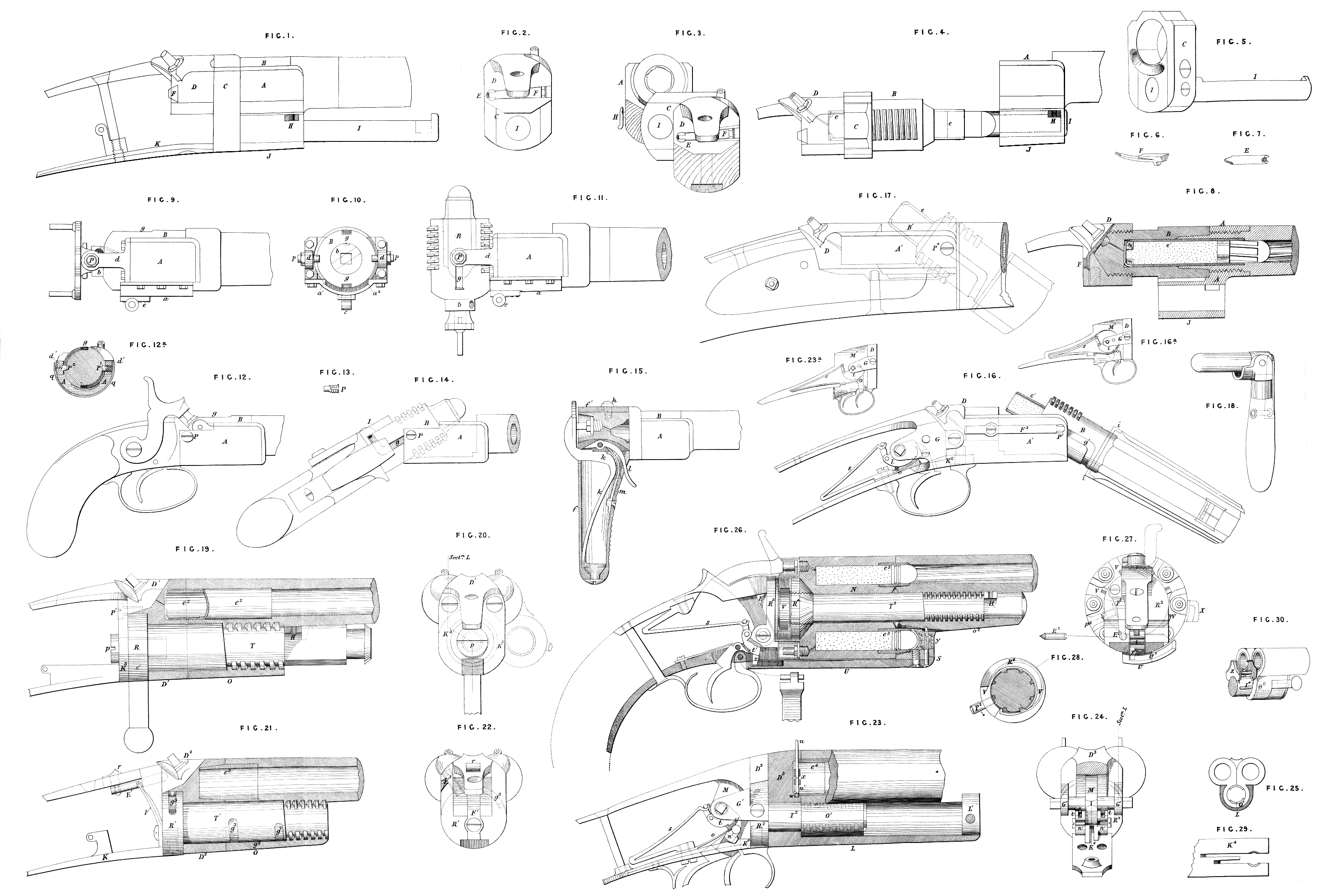
My improvements refer mainly to breech-loading fire-arms in which the breech or breech chamber is connected to the barrel by means of a screw having portions of the external and internal threads cut away so that the one will slide longitudinally within the other and then inter- lock by a partial turn; but some of the improvements are applicable to other breech loaders. They are illustrated in the accompanying Sheet of Drawings which I shall briefly describe.
Fig. 1 is a side view or elevation, and Fig. 2 a rear view of the action as used in the first method of construction in its closed state; Figures 4 and 3 corresponding views when open. In Fig. 3 part of the wood of the fore end and stock proper is shewn; Fig. 4 shews the cartridge e as introduced; Fig. 5 the collar C and spindle I; Figures 6 and 7 the stop pin E and spring F, the last three in perspective. Fig. 8 shews in partial section a modified form of the action, Fig. 1, C and I, being left out. The cartridge e^1 has a wooden or metal ring inserted in the rear to prevent collapse when withdrawn.
Fig. 9 is a side and Fig. 10 an end view of part of a field gun constructed on the second or centre swivelling method in its closed state; Fig. 11, a side view of same when open and loaded; Fig. 12^a shews in section a scoop-shaped piece q, which may be fixed to the break- off and nipple lump in small arms made on this principle, so as to cover the straps or brackets d^1, which are here forged or cast with the breech case.
Figs. 12 and 14 are side views of a preferable arrangement as applied to pistols. Fig. 12 shews the closed, Fig. 14 the open and loaded, state; Fig. 13 shews an elastic screw pin P^2 made with a slit and slightly opened out so as to have a better hold.
Fig. 15 shews in section part of a walking-stick gun, the breech of which is locked to the barrel in a similar way, but without the guide grooves and swivelling pins; Fig. 16 is a side view of the inverted action. Fig. 17 shews another form of same fitted with a bar lock. Fig. 18 is a sketch of a cartridge extractor.
The third mode of construction is shewn as applied to double barrels in Figs. 19, 21, and 23, which are partial sections taken mainly on the dotted. zig-zag lines shewn in Figs. 20, 22, and 24, which are rear views of the above actions. In Fig. 24 the trigger plate is shewn, but without the springs s and o. A wooden fore end is required for the form, Fig. 19, and may be fastened in any known way; Fig. 25 is a reduced section at the rear of the barrels in Fig. 23.
Fig. 26 shews in partial section the fourth or revolver construction; Fig. 27 a rear view of the action; Fig. 28, the recess in the bolt head, in which the actuating spring is placed.
Fig. 29 shews in plan the slotted end of the trigger plate, Fig. 23; Fig. 30 is a reduced perspective sketch of one of the forms used with a flange cartridge, and the extractor employed; Fig. 16^A is a reduced side view of a lock for a single gun, modified from that shewn in Fig. 23.
Fig. 23 , another modification for double gun.
In the first method of construction, Figs. 1, 2, 3, 4, 5, 6, 7, 8, the rear of the barrel is formed or fitted with a breech case A, similar to that described in the Specification of a Patent granted to Andrew Wyley, and dated the Second of October, One thousand eight hundred and sixty-one, No. 2453, and figured in Sheet I. of the Drawings attached to same, with the exception that it is shorter, not extending further back than the screwed part, and has attached to its lower portion a lump J of a depth equal to that of the wooden “fore end,” The breech chamber B, which for brevity I may call the breech, is also formed like that described and shewn in said Specification and Drawings, but it is without the lever, and firmly attached to the stock by: means of a piece D, which takes the part of the ordinary break-off, and which a may be so called. The charge chamber is usually carried a small way into D, in which the nipple or percussioning is so placed as to bring the fire as nearly central as possible. A backwork lock is used. In this form and in those to be described wherever B is of a length to contain the greater part of the charge, the same variety of ammunition maybe used as with the fire-arms described in the Specification above referred to; the paper-covered opening in the rear of the thick cartridges being sometimes made larger where the fire is not quite central. As such stout cartridges when exploded remain in B, and are not always extractable by the hand or by the teeth, an extractor, Fig. 18, is used; it consists of a plug, which enters into the cartridge, and has at its end a moveable jaw, which is made to bite it outside by drawing back the lever handle attached to said jaw, and then by a forward motion of the whole the cartridge is drawn. The jaw is kept open by a spring as shewn. The fore part of the cartridge may be lined with sheet brass. The stock is divided in front of D, and between the fore and rear parts a carrier or collar C is placed embracing a reduced zone of the breech between the screw and D; a spindle I screwed or driven into C travels in a hole in the lump J. The collar is made in two parts, joined by screws. To open the breech the stock is turned one-quarter round, by which the screw is disengaged. Stock, breech collar, and spindle are then drawn back and made to swivel to the right round the axis of I, into the positions shewn in Figs. 3 and 4, when the old cartridge is replaced by a fresh charge. The closing is effected by reversing the above motions. The cartridge e may be inserted a short way in the barrel, or as far as the chambered part will admit, and B slid over it. When exploded it remains in B, unless where the expanding lip is reversed, as shewn in Fig. 8; it here stays in the barrel, and is drawn by hand. The chamber in B should taper slightly towards D. When e or e^1 is first inserted in the barrel al mechanically-fitting ball may be used. A spring stop holds the breech when in the locked position, and that in which it is withdrawn Figs. 2, 3, 6, and 7. The pin E works in a hole in D, and is pressed by the spring F against the collar C, and when D is turned it falls into two holes corresponding to the above positions. The sides of the holes are sloped towards each other, so that E can rise out of them when the stock is forcibly twisted round Fig. 5. The spring F is placed in a recess in D, and held by its lower blade entering a dovetail, and secured by the lock-plate fitting against the projecting stud. The above stop maintains the position of D in respect to C, the last is prevented from turning when being drawn out, by having a flat formed on the spindle I, which flat works against the transverse bolt H; when fully withdrawn a gap cut on one side of I allows it to swivel to the right. H is only a strong form of the bolt used to connect the fore end to the barrel; its head should project so that it can be easily drawn to one side to allow the arm to separate: into two parts. The wooden fore- end is held by H and another bolt farther: forward, or by any known means. A hole is bored in it to admit the spindle, and fitted with a cork or india-rubber pad to receive the end of I. I sometimes screw or otherwise fit the breech into D, Fig. 8, the percussioning crossing the joint. Central fire is readily obtained, as when the breech is unscrewed the communication may be drilled more obliquely than usual. The collar C may be formed in one piece, an object which can also be attained by making the screw-joint in advance of C; this form also admits of the use of a steel breech, hardened and tempered in oil. I may here observe that I sometimes form the breech- case A or other part of the ” action ” as B, Fig. 16, in one piece with the barrel, both being of steel, and harden and temper such parts usually up to or a little beyond the fore part of the charge chamber. For this purpose. two heavy metal rings are used of a size to fit the heated barrel near the rear end. One, an iron ring, is placed on the barrel when in the fire, and prevents the heat extending too far. The heat is got up rapidly, the iron ring knocked off, and a cold ring of brass or iron. slipped on and turned round on the same part for a short time, in order still further to define the junction between the red hot and cooler parts of the barrel before it is immersed in the hardening fluid.
In the second mode of construction the parts J, C, and I are dispensed with. It is shewn as applied to ordnance in Figs. 9, 10, and 11. Two straps or brackets d extend backwards from A carrying the pins P near their rear end. The inner ends of these pins enter e grooves g when B is drawn back after. being unscrewed; when drawn back far enough B may be tilted up for loading oscillating on the pins P, until it is stopped by coming against the bottom part of B, a, Fig. 11. By prolonging a the tilting may be stopped at any angle from about thirty degrees to ninety degrees. The part a has its left-hand angle cut away a^1 so as to allow the screw threads to pass when B is unlocked; they are stopped by coming against the other angle a^2 ; when B is drawn back the screw slides in a as a bed. The requisite motions are: given to B by handles as shewn at its rear end, at the same time capstan holes are formed in the cylindrical button b, or a single hole is formed quite through it, Figs. 9 and 10, into which a strong steel-shod lever may be shipped when the gun is required for service. The position of the pins P and length of the grooves g are so adjusted that when Bis drawn out to its full extent its rear overbalances the fore part, so that it tilts without force; when the charge is introduced the balance should be nearly even. By changing the position of the parts ninety degrees B may be made to swing to one side instead of tilting, the lower bracket being more strongly attached. I prefer to line the chamber with a tube of steel hardened in oil and brought to a low spring temper, and driven as tightly into B as possible; the fore part projects and enters into the main tube of the gun, as in small arms; the elevating screw is attached to c.
In small fire-arms the breech B is moved by the stock to which it is attached, as in the first method. The brackets or straps d are made of one piece with A, the whole being preferably of circular outline, the fore end of the stock being dispensed with. A covering piece q, Fig. 12^a, may be attached to the break-off. But a better arrangement is shewn in Figs. 12 and 15, as applied to a small pistol, wherein the straps d are continued downwards forming a simple extension of the breech case, but without any screw cut in it. This part is so cut away as to allow the breech to tilt up to an angle of thirty degrees, or so far as to allow of its being loaded, as shewn in Fig. 14. Guide grooves g are cut for the pins P^2 as shewn. In larger fire-arms the nipple is placed further back, a backwork lock may be used and a divided stock, as in the first method.
In the walking stick gun, Fig. 15, a cross handle f takes the place of the stock. It is conveniently made of cast metal with a tubular ring f^1, which is fitted to a reduced part of the breech and fixed by the screw h. It is removable in order to introduce the lock, the principal part of which is a main spring k with crank-shaped head striking directly on the nipple. The trigger sear 7 is first placed in a recess in the neck of the breech; the main- spring is introduced into f, and the sear spring m attached, f is then fixed in its place, the sear spring being sprung over the head and eye of the sear.
In pistols or walking stick guns made without pins and grooves the breech is quite separated from the breech case in loading, but they are linked together by a chain or other flexible connection.
The foregoing construction may be varied by reversing the action, as in Figs. 16 and 17. The pins are in advance of the breech case or its screwed part, and work in guide grooves g^1 in the barrel. In Fig. 16 plain pins P^1 acted on by the spring F^3 are shewn working in shallow grooves g^1 deepening at the ends, B^1 may be screwed into the main part of the barrel with an escutcheon plate i between to cover the opening between A^1 and B^1. It may have a raised rim, as in Fig. 16, to retain a thin wooden casing, the fore part of which may be inserted in a hollow metal nose cap soldered to the barrel. Where no wood is used the barrel should have a projection below it to afford a good grip: The cartridge used for this gun may be the same as e^1, Fig. 8, or in place of a ring a short metal tube may be inserted, as shewn; its rear passes a considerable way into D; it is manipulated the same way. A steel tube may be used to cross the joint as e^3 in Fig. 21, when a skin or paper cartridge may be used. The percussioning is, as in the first method, the communication being drilled directly from the centre of the nipple seat, so that the fire can pass through the thin paper covering the end of the cartridge. If a cartridge is used with the arm Fig. 12 the same percussioning is used.
In double-barrels, as the connecting screw cannot well be placed on the barrels so as to take the strain directly, it is placed on a strong bolt T of hardened and tempered steel passing through a hole in a deep break-off, and engages in an internal screw in a lump O, firmly attached to the barrels below their rear end in any known way. In the Figs. 19, 21, 23, and 25 the said lump O, O^1, is supposed to be forged one-half with each barrel, and well brazed along the middle line. Portions of the screw threads are cut away as before, so that when the bolt T is turned one quarter round it may be drawn back in O, carrying with it the break-off and stock or butt of the fire- arm, which are thus separated far enough from the barrels to allow the latter to swivel on T to the right and left for loading in the forms shewn in Figs. 19 and 21, or to be loaded without swivelling, as in Fig. 23. The bolt H passing through a loop on each barrel, and working against a flat surface with suitable gaps formed on T, as shewn in Fig. 19, or a pin like P^1 or P^2, Figs. 14 and 12, the end of which enters a suitable groove g^2, Fig. 21, act as guides and stops to restrain the above motions within the necessary limits. The barrels are usually formed with cones or tubular lips to enter the break-off, or vice versa. The lip may be a steel tube e^3 firmly fixed in the barrel, Fig. 21, which admits of the use of a thin combustible cartridge. The cartridge e^2, Fig. 19, is similar to e^1, Fig. 8, but is fitted with a thimble of copper, brass, or charcoal iron long enough to cross the joint. If the cartridge is of thin paper the thimble should be of twice the length shewn in Fig. 19. When a lever is used to work the bolt T, as in Fig. 19, it extends downwards from the circular head R of the latter, which turns in a recess in the rear of D^1. The lower strap forming the trigger plate is bent upwards nearly at right angles in the form of a plate K^3 of an outline similar to D^1; K^3 is attached to D^1 by screws p^1. A strong pin p passing through and capable of turning in K^3 is screwed very tightly into the centre of R, and gives additional strength. In loading the right-hand barrel, which is then in the position shewn by dotted lines in Fig. 20, the lever is turned back into the locking position. The lever may be dispensed with, Figs. 21, 22, 23, and 24, the stock firmly attached by upper and under straps to the bolt head giving the requisite motion. The break-off D^2, D^3, is here a separate piece; to prevent R^1, Figs. 21 and 22, drawing away from D^2 a pin E^3 is screwed into the latter, and its end works in a groove g^3 in the circumference of R^1. In Figs. 23 and 24 the same object is attained by making the upper part of R^2 of a conically bevilled form ; the under strap being removed the bolt is inserted with the upper strap downwards and turned round into its place. A spring stop, shewn in Figs. 21 and 22, may be used; the spring F^1 presses the bolt E^1 into a hole in D^2, when the screw is locked E^1 is drawn back by the thumb-piece r.
In order to take the bending strain off the bolt, the break-off part D^3, Fig. 23, is sometimes continued to form a hollow body or bed L of the section shewn in Fig. 25. The barrels are shaped so as to slide along its upper part parallel to the axis of L, and are prevented from having lateral motion by the lump O^1 sliding in the tubular channel of L. The bolt T^2 attached to the stock as before engages in O^1; by a quarter turn it is unlocked, the barrels and lump O^1 are then free to slide forward far enough to admit the cartridge; O^1 is stopped by a closing piece L^1 fitted in the fore end of L. The trigger guard is so disposed as to come against the edge of the arched part of D^3 when the screw is fully unlocked and no other stops are required.
The cartridge e^4 , Fig. 23, is fitted with a metal thimble, and the percussion powder is placed between two pins u and u^1, the joint is covered by the short tube x, having a notch in front through which the composition may be introduced. A shallow hole w may be formed in D^3, into which the pin u^1is driven by the hammer, so as to draw the cartridge when the barrels are pushed forward; e^4 is finally removed by hand. The ordinary pin cartridge may be used, D^3 being left plain.
In this construction, and wherever the lock action can be brought near enough to the break-off I construct the lock as follows:— Instead of lock plates two short cheek pieces G^1 are screwed to the bolt head or break-off; these carry the external arms of the tumblers t, while the inner studs are borne in a middle piece M standing up from the lower strap, or extending between the lower and upper straps. The main springs S are attached to the middle piece M or lower strap K^4 as in Fig. 23; the trigger sears n^1 are carried on pins screwed into or passing through M, and are acted on by springs o, usually made in one piece with the mainsprings, or fastened by the same screw, as shewn in Fig. 23. The trigger sears, Fig. 23, are shewn as cranked, so as to bring the trigger blades closer together. The slots are cut from the end of K^4, see Fig. 29, and the gap thus left before the triggers when in place is filled up by a projection on R^2, through which the attaching screw passes. The screw is made large enough to grip K^4 on each side of the slot; if applied to a fire- arm, in which the stock is fixed to the break-off; G^1 and K^4 are also attached to the latter. The cheeks and trigger plate are attached to the bolt head, as indicated in Figs. 23, 24, so as not to break its outline or prevent its turning.
In revolvers, Fig. 26 and 27, the connecting bolt T^3, the round head of which turns in a recess in a cylinder, and is attached by upper and lower straps to the stock forms the spindle on which the cylinder N rotates. It screws into a lump O^2 below the barrel; O^2 is continued downwards to form an abutment S to diminish the lateral strain on T^3. The barrel is formed with a conical lip or short tube at its rear end entering some way into each chamber, so as to break the joint; or each chamber may have, as shewn in Fig. 26, a fixed projecting tube e^3 entering a short chamber in the end of the barrel. When one of these enters the barrel the others enter a perforated shield attached to the rear of the latter, of which S forms part. The action is as follows:— When the handle or stock of the fire-arm is turned one quarter round the screw is disengaged, T^3 is drawn back, carrying with it the chambers till they and as much of the charge as may project from them are clear of the shield and barrel. The motion of turning the stock compresses a circular- shaped spring V, Figs. 26 and 28. The fixed end of the spring, or what may be regarded as such is connected to N by the screw pin p^2 the other or free end is furnished with a click falling into ratchet-shaped notches in the reduced part of the bolt head. The spring being in the position shewn in Fig. 28, if T^3 is turned round to the left no compression takes place until the click falls into the first notch, further turning brings the spring into the position shewn by the dotted lines in Fig. 28. When the stock is drawn back as soon as the lips of the chambers are clear of the barrel, N is free to revolve on T^3 and the reaction of the spring V carries N round until the second chamber is opposite or nearly opposite to the barrel. The sloping side of the ratchet notches is made somewhat abrupt, requiring force to draw out the click, which counteracts the tendency to overshoot when the parts work freely. A spring F^2 Fig. 27, is used, and acts on a pin E^2, like that shewn in Fig. 7, which falls into V notches v in N to assist in bringing it up, so that a chamber is opposite to the barrel. Should N overshoot or stop short it is adjusted by hand. In relocking the screw the click of V is drawn out of one notch, passes over another, and nearly reaches a third, when it is in a position to act afresh. The head of the spring V^1 being screwed up to N by the pin p^2 keeps R^4 in its place The last is shewn as removeable, in order to get the spring V into place; or R^4 may form part of T^3, in which case R^3 is made strong enough for the reduced part of the bolt head to be screwed into it. A stop H is used to confine the motions of T^3, as in former constructions. The fire- arm may be cocked by hand before unscrewing, or it may be made self- cocking. With this view an arm or stud z is made to project from the bottom of the tumbler t^1. When the stock is turned to unscrew, z travels in a broad transverse groove U^1 in the hinder part of a scoop-shaped piece U, forged with or fixed to the shield or the abutment S. The posterior side of the groove is inclined, so that z being forced to travel against it brings the hammer to full or half cock, as arranged. Instead of this a strap X, Fig. 27, may be fixed. in the same way as U, but at one side of the cylinder. Into a groove in the rear of this the stud passes when the stock is turned a quarter round. When the stock is drawn back z is caught by X, and the hammer cocked as before. In this arrangement, as in turning the stock round to unscrew, the hammer is liable to catch, the nipples should project slightly beyond the recesses. The face of the hammer should be inclined on the left side, so as to spring over them, its lower part at other times travelling against the annular back of N. The hammer tumbler t^1 is pivotted as low and as far forward as possible. By withdrawing the stop the cylinder is removeable for loading, which is done by hand. In Fig. 27the shield openings are represented: as fitted with wooden plugs y, to prevent the bullets from coming out. The shield and plugs y may be dispensed with, in which case a lever ramrod maybe more readily used; metallic cartridges projecting from the chambers may be used, instead of the tubular lips, a strong jaw tool like that shewn in Fig. 18, but with the jaw on the opposite side being used to extract them. Instead of a poly-chambered cylinder, I sometimes use a pair of chambers only, which are rotated by hand, their lips entering in turn the barrel and piece S. The bolt acts the same as T^3; a pin takes into a groove in the head to prevent it separating from the chambers. The revolving and cocking gear are dispensed with, and an ordinary lock may be used, the percussioning being as in the first method.
Having now described several modifications of fire-arms constructed ac- cording to the above Invention, I would observe that I do not confine myself to these forms, which may be easily varied to suit circumstances. Thus, as examples in the first and second methods, the locking screw may have only two partial threads, if these are made strong enough. The construction shewn as applied to double is applicable to single barrels, the tie bolt, engaging in a strong lump forged on the rear of and below the barrel. The lever bolt T, Fig. 19, may be reversed, its screwed part engaging in D, or a fixed nut behind it. A guide pin may be screwed into D^1 working in suitable grooves in the plane part of T; the part D^1 may be made long enough to contain the entire charge; T is placed so as to leave room for the bolt head under the barrels, also the bolt T being a fixture projecting from the break-off, the locking may be by a round lever nut turning between O and a retaining piece below the barrels, and engaging with the screwed part of T, which is made somewhat smaller; or T itself may be placed lower, to allow of room for said nut. This construction is well suited for a flange cartridge, the break-off being made plane, and screwing up directly against the barrels. A suitable extractor Z is shewn in Fig. 30. The head fits into a recess in the barrel ends as usual, and the stem slides in a hole formed in the space between the barrels and bolt T^4. The lower part of the head is curved to fit T^4, and moves round it
with the barrels when the latter swivel to right and left for loading. A
circular transverse feather on T^4 enters a corresponding but wider groove in; the lower curve of the head, and draws the extractor and cartridges away from the barrels when the stock and T^4 are drawn back, the stock being turned sixty degrees to the right and left the cartridges are extracted by hand. A guide pin may be placed near the rear of O working in a T-shaped groove in the bolt. When the nut is unscrewed the lever is stopped by a projection on the barrel, or on O. Whenever a lever is used it should be held in one hand when barrels and stock are separated, or else it should work with considerable friction. The form, Fig. 21, is adapted to a flange cartridge by dispensing with D^2, the bolt head k^1 being made a plain break- off screwing up against the barrel ends, and retained by friction, or a spring stop. When the bolt is unlocked and drawn back the right-hand cartridge may be withdrawn. By turning the stock and bolt thirty degrees further in the same direction as before, the left-hand cartridge is exposed. An extractor similar to that above described is used. A spring stop like that shewn in Fig. 16 is used, a suitable guide groove being formed with holes deepening at the positions of loading and locking.
Flange fire and central fire cartridges on Schneider’s or any similar plan may be used. Needle fire and needle fire cartridges may be used with nearly every form of the fire-arm, the percussive arrangements being modified to suit.
The action shewn in Fig. 16 is applicable to the lighter kinds of ordnance, the breech case A^1 being fitted with levers instead of a stock. The lock shewn in Figs. 23 and 24 may be variously modified. Thus the middle plate M may be extended into a broad vertical blade M^1, Fig. 23^a, extending quite through the stock, till at some distance beyond the swivels it narrows abruptly, and is continued backwards in the form of a long taper tang entering far into the stock. The broader part may be thicker and ground out slightly hollow on both sides, the better to hold the wood which is screwed tightly up to it by a side pin passing through from cheek to cheek G^1; upper strap and trigger plate are dispensed with, being merged in M^1; the main springs are fixed to opposite sides of M^1 as to a lock plate, the tumblers as before the trigger sears extend downwards on each side of M^1, and may be straight or cranked outside the lower edge of M^1, in which a notch may be made, to allow of their back play. The gaps in the stock left for the sears to enter when the stock is driven up to its place may be filled up with block pieces screwed to M^1, or covered by a plate screwed to the lower part of M^1 In a single lock on this principle, Fig. 16^1, M^1 being as before, a round hole is cut in it large enough for the play of the tumbler and sear end, which hole is continued backwards far enough to admit the main spring, which may be fixed by a dovetailed foot entering M^1, the straight trigger sear is inserted through and works in a slot in the lower limb of M^1. The sear springs may in both single and double.forms be part of the main spring, or be fixed to M^1 in any known way. One arm of the tumbler is carried in a side plate as before, the other may mounted on an opposite side plate, or on a slip screwed to M^1 on the left side. A side pin is screwed into the right-hand cheek to make all fast as before. In the lock shewn in Fig. 16 the middle piece N, Fig. 23, is represented by a small plate standing up from the trigger plate, a little to the left of the central line, or extending back from the break-off D, which plate carries the inner stud of the tumbler and sear pin. The trigger sear passes through a slot in the trigger plate.
The arrangements in the above-described fire-arms which I claim as new are as follows:—
Firstly, as regards the first method of construction I do not claim the collar C with its spindle I and stop H; neither do I claim the method of locking the barrel and breech case to the breech by a screw in sections, as shewn, but what I claim is, the employment of such screw in connection with a collar and spindle placed as above shewn, the said collar being in the rear of the locking arrangement.
Secondly, I claim the employment of a similar breech-locking arrangement in connexion with guide grooves and swivelling pins mounted as set forth and shewn, also the particular constructions exemplified under the second head of this Invention, and shewn in Figs. 9, 10 and 11, 12, 14, 15 and 16.
Thirdly, I claim the application of the bolt T to closing the breech in double barrels or single guns, as above described and set forth, and the particular constructions by which it is exemplified.
Fourthly, I claim the application of a similar bolt to revolving fire-arms, and the mode of construction of the parts in connection therewith for revolving and cocking, shewn in Figs. 26, 27, and 28.
Fifthly, I claim the application to breech-loading fire-arms of the central locks with outside hammers, described and shewn in Figs. 23 and 24, with the modifications shewn wherever the locks can be brought moderately near to the break-off, and where the latter and the wood of the stock are of sufficient depth.
In witness whereof, I, the said Andrew Wyley, have hereunto set my hand and seal, the Sixteenth day of January, in the year of our Lord One thousand eight hundred and sixty-five.
ANDREW WYLEY. (L.S.)
Witness,
J. W. MOFFATT,
66, Chancery Lane.