
A.D. 1867, 3rd APRIL. № 1007.
Revolving Breech-loading Fire-arms.
LETTERS PATENT to William Robert Lake, of the “International Patent Office,” No. 8, Southampton Buildings, Chancery Lane, in the County of Middlesex, Consulting Engineer, for the Invention of “Improvements In Revolving Breech-Loading Fire-Arms.”— A communication from abroad by William Herrick, of the City, County, and State of New York, United States of America.
Sealed the 24th September 1867, and dated the 3rd April 1867.
PROVISIONAL SPECIFICATION left by the said William Robert Lake at the Office of the Commissioners of Patents, with his Petition, on the 3rd April 1867.
I, William Robert Lake, of the ” International Patent Office,” No. 8, Southampton Buildings, Chancery Lane, in the County of Middlesex, Consulting Engineer, do hereby declare the nature of the said Invention for “Improvements In Revolving Breech-Loading Fire-Arms,” a communication, to be as follows:—
The said improvements relate more especially to pistols which have a revolving cylinder containing a series of charge chambers arranged behind a fixed barrel, and consist chiefly in the peculiar construction of the said cylinder, which is made in two concentric portions. One of these portions is fitted to slide forward over the inner portion or core, which revolves on a central pin or axis. The division of the cylinder extends only for a portion of its length. The rear portion of the charge chambers is formed half in the core and half in the outer portion of the cylinder, the said chambers being continued forward beyond the end of the core into the solid front end of the cylinder. The cartridges employed are of such a length as to extend into the said solid portion of the cylinder, which sustains the whole force of the explosion. The charge chambers are formed with a recess at the rear end to receive the rim or flange of the cartridges.
The said improvements further consist in providing the under side of the barrel in front of the cylinder with a longitudinally grooved projecting piece, which is formed with an inclined recess and arranged to operate in combination with a stud or finger on the centre pin or rod whereon the barrel is turned to release the sliding portion of the cylinder. The barrel is locked when the pistol is adjusted for firing by a spring catch secured in the projecting piece and arranged to take into the end of the breech frame.
The inner portion or core of the cylinder is formed with a flange which when the breech is closed fits closely to the outer portion of the said cylinder; this inner portion or core is fitted to turn freely upon the centre pin or rod, and is provided with a collar which extends into the stock, and is fitted with a key to keep the said core properly up to the back plate and prevent its moving endwise. The inner portion or core of the cylinder extends about half way through the same.
The outer portion of the said cylinder is formed with a recess extending about half way through to receive the core or inner portion, and the two portions are so formed that when the breech is closed the two halves into which the series of chambers is divided fit perfectly together and coincide exactly with the continuation of the said chambers formed in the solid portion of the revolving cylinder. The inner portion or core of the cylinder is furnished with a guide pin or key which fits a longitudinal groove in the outer portion and keeps the two halves into which the chambers are divided properly together. The latter is provided with a collar which turns upon the centre pin and extends into the projection on the under side of the barrel. A key or feather passed through the said projecting piece into a groove in the said collar unites the barrel firmly to the cylinder, but allows it to turn independently upon the centre pin or axis. The centre pin is firmly secured to the breech frame and extends through the cylinder and through the projecting piece on the under side of the barrel. The front end of the said pin is provided with a stud or finger which fits a longitudinal groove in the lower side of the said projecting piece. The said stud also fits an inclined lateral recess extending through the side of the projecting piece into the front end of the longitudinal groove. The rear end of the projecting piece of the barrel is furnished with a spring catch, which is arranged to enter a recess formed in the front of the breech frame and lock the barrel to the said frame in the proper position for firing. The said catch is formed with a knob or projection which is pressed inward when it is desired to receive the barrel. The latter may be then turned on its axis till the stud on the centre pin is in line with the longitudinal groove in the projecting piece; the barrel can then be pushed forward and will draw the outer portion of the cylinder away from the core or inner portion of the same; the empty cartridge cases can then be readily removed and the chambers filled with fresh cartridges; the barrel is then turned on its axis to the proper position for firing, and at the same time the inclined grooves acting on the stud of the centre pin forces the barrel back and brings the outer portion of the cylinder closely and securely in contact with the flange on the inner portion or core; the barrel is then locked by the spring catch and is ready for firing. The rotation of the cylinder to bring each chamber in line with the barrel is effected by the ordinary mechanism in connection with the cock or hammer.
SPECIFICATION in pursuance of the conditions of the Letters Patent, filed by the said William Robert Lake in the Great Seal Patent Office on the 1st October 1867.
TO ALL TO WHOM THESE PRESENTS SHALL COME, I, William Robert Lake, of the ” International Patent Office,” No. 8, Southampton Buildings, Chancery Lane, in the County of Middlesex, Consulting Engineer, send greeting.
WHEREAS Her most Excellent Majesty Queen Victoria, by Her Letters Patent, bearing date the Third day of April, in the year of our Lord. One thousand eight hundred and sixty-seven, in the thirtieth year of Her reign, did, for Herself, Her heirs and successors, give and grant unto 3 me, the said William Robert Lake, Her special licence that I, the said William Robert Lake, my executors, administrators, and assigns, or such. others as I, the said William Robert Lake, my executors, administrators, and assigns, should at any time agree with, and no others, from time to time and at all times thereafter during the term therein expressed, should and lawfully might make, use, exercise, and vend, within the United Kingdom of Great Britain and Ireland, the Channel Islands, and Isle of Man, an Invention for “Improvements In Revolving Breech-Loading Fire-Arms,” upon the condition (amongst others) that I, the said William Robert Lake, my executors or administrators, by an instrument in writing under my, or their, or one of their hands and seals, should particularly describe and ascertain the nature of the said Invention, and in what manner the same was to be performed, and cause the same to be filed in the Great Seal Patent Office within six calendar months next and immediately after the date of the said Letters Patent.
NOW KNOW YE, that I, the said William Robert Lake, do hereby declare the nature of the said Invention, and in what manner the same is to be performed, to be particularly described and ascertained in and by the following statement, reference being had to the accompanying Sheet of Drawings forming a part of this Specification:—
The said improvements relate more especially to pistols which have a revolving cylinder containing a series of charge chambers arranged behind a fixed barrel, and consist chiefly in the peculiar construction of the said cylinder, which is made in two concentric portions; one of these portions is fitted to slide forward over the inner portion or core, which revolves on a central pin or axis. The division of the cylinder extends only for a portion of its length. The rear portion of the charge chambers is formed half in the core and half in the outer portion of the cylinder, the said chambers being continued forward beyond the end of the core into the solid or undivided front end of the cylinder. The cartridges employed are of such a length as to extend into the said solid portion of the cylinder, which sustains the whole force of the explosion. The charge chambers are formed with a recess at the rear end to receive the rim or flange of the cartridges.
The said improvements further consist in providing the under side of the barrel in front of the cylinder with a longitudinally grooved projecting piece, which is formed with an inclined recess and arranged to operate in combination with a stud or fin on the centre pin or rod whereon the barrel is turned to release the sliding portion of the cylinder. The barrel is locked when the pistol is adjusted for firing by a spring catch secured in the projecting piece, and arranged to take into the end of the breech frame.
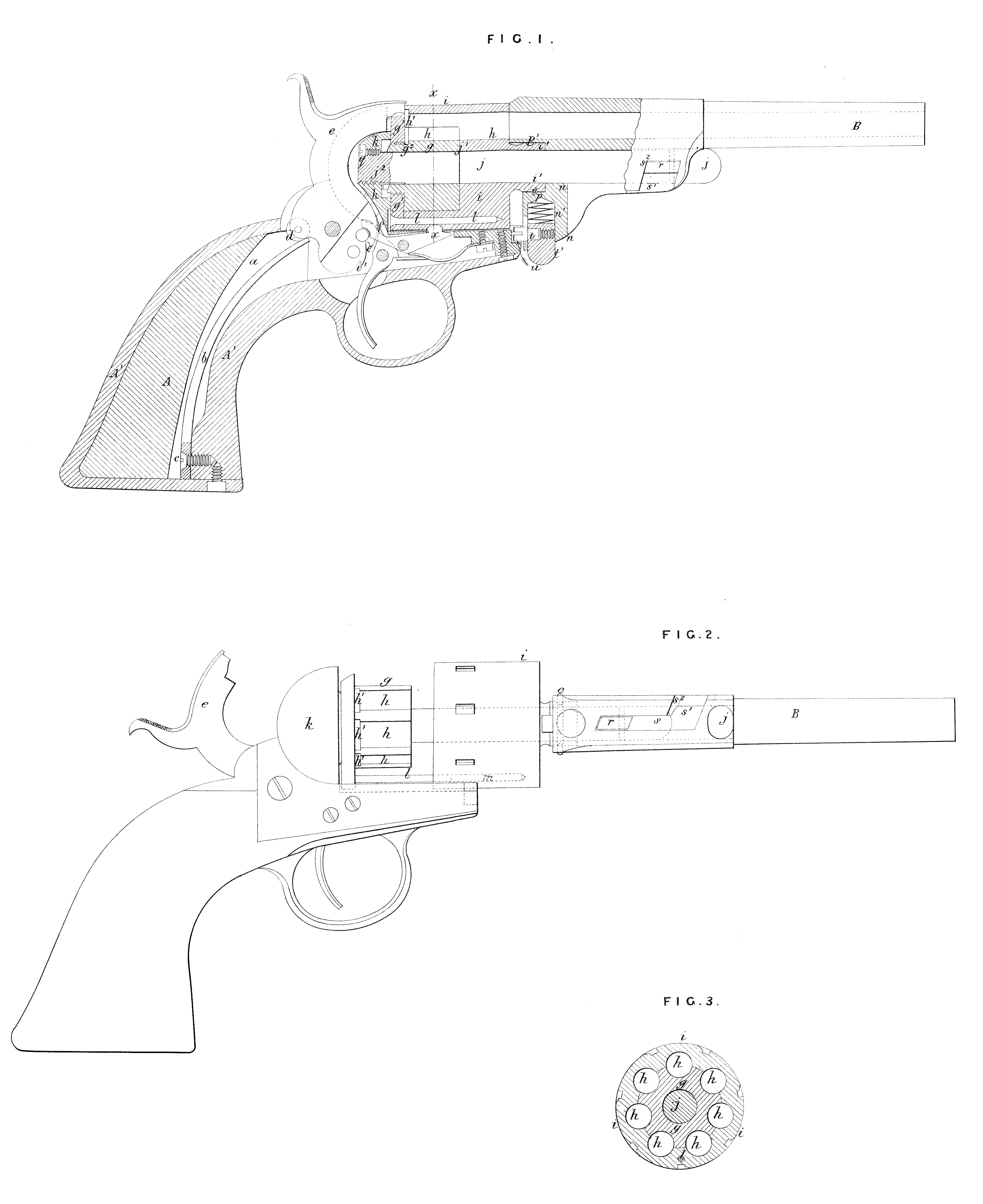
DESCRIPTION OF THE DRAWINGS.
Figure 1 is a side view of my improved pistol with the barrel and revolving cylinder adjusted for firing; Figure 2 is a side view of the said pistol, showing the barrel and cylinder adjusted for loading; Figure 3 is a section of the revolving cylinder on the line x, x, Figure 1. Like letters indicate the same parts in each of the Figures.
A is the stock, which may be of any suitable form and construction. The chamber a in the said stock is provided to receive the mainspring b, which is attached to the stock at the lower end of the said chamber by a screw c or other convenient fastening. The free end of the mainspring acts upon the friction roller d on the hammer e, which is held at full or half cock in the ordinary manner by the point of the sear f resting in either of the notches e^1, e^2. The inner portion or core g of the cylinder is provided with a flange g^1, which may be screwed upon a neck or projection g^2, as shown in Figure 1, or formed solidly upon the said core. When the breech chambers h are closed this flange fits closely to the outer portion i of the revolving cylinder. The inner portion or core g is fitted to turn freely upon the centre pin or rod j, and is kept up against the back plate k by the shoulder j^1 of the said centre pin, or by means of a collar extended into the stock and fitted with a tangent key in such a manner as to keep the part g from moving endwise. The inner portion or core g extends about halfway through the revolving cylinder, and the outer portion i of the said cylinder is bored or chambered to the proper length to receive the said core or inner portion. By making the core g shorter than the cartridges the accumulation of dirt between the two portions g and i is prevented; these two portions are so formed that when the breech chambers are closed, as represented in Figure 1, the two halves into which the chambers h are divided fit perfectly together, and coincide exactly with the continuation of the said chambers formed in the solid or undivided end of the outer portion of the revolving cylinder. The inner portion or core g of the said cylinder is furnished with a guide pin or key l, which fits a hole m or a longitudinal groove in the outer portion i and keeps the two halves g and i properly together. The outer portion i of the cylinder is provided with a collar i^1 which turns upon the centre pin j and extends into the projection n on the under side of the barrel B. A key or feather o passed through the said projecting piece into a groove p in the collar i^1 unites the barrel B said projecting piece into a groove p in the collar securely to the outer portion i of the said cylinder, but turn independently upon the centre pin or axis j. allows the barrel to The centre pin j is preferably formed with a screw thread j^2, whereby it is firmly secured in the back plate / or other convenient part of the breech frame A^1, a small screw q being inserted at the exterior of the screw thread to prevent the turning of the rod j. The latter extends through the cylinder and through the projecting piece n on the under side of the barrel B. The front end of the said pin is r provided with a stud or fin r, which fits a longitudinal groove s in the lower side of the said projecting piece. The said stud also fits an inclined lateral recess s^1 extending through the side of the projecting piece n into the front end of the longitudinal groove s. If found desirable two of these studs r, grooves s, and recesses s^1 may be provided. The rear end of the projecting piece n of the barrel B is formed with a chamber or cavity n^1 to receive the spring catch t, which is arranged to enter a recess u formed in the front of the breech frame A^1, and lock the barrel to the said frame in the proper position for firing, as shown in Figure 1. The said catch is formed with a knob or projection t^1, which is pressed inward when it is desired to release the barrel B. The pistol is loaded when the parts are in the position shown in Figure 2, the cartridges being inserted into the chambers h with their rims resting in the recesses h^1, and their ends extending into the undivided end of the portion i of the cylinder. The barrel B is then turned on its axis j to the position shown in Figure 1. The side s^2 of the inclined groove s^1 acting on the stud or fin r of the centre pin j forces the said barrel back and brings the outer portion i of the cylinder closely and securely in contact with the flange g^1 on the inner portion or core g. The barrel B is then locked by the spring catch t, and is ready for firing. To empty the charge chambers h, and reload the pistol, the barrel is released and turned on its axis till the stud r on the centre pin is in line with the longitudinal grooves; the barrel B can then be pushed forward, and will draw the outer portion of the cylinder away from the core or inner portion g. The empty cartridge cases can then all be readily removed, and the chambers A filled with fresh cartridges. The rotation of the cylinder to bring each chamber in line with the barrel B is effected by the ordinary mechanism in connection with the cock or hammer e.
Having thus fully described the said Invention as communicated to me by my foreign correspondent, and shown how the same may be conveniently and advantageously carried into practice, I wish it understood that I do not confine myself to any particular form or arrangement of the parts of the lock or devices for causing the rotation of the cylinder, nor to any of the details of construction relating to the barrel, stock, or other parts common to all pistols, nor do I claim any part of the same, but I claim,—
First, constructing the revolving cylinder in two portions, substantially as and for the purpose set forth.
Second, making the core or inner portion g of the revolving cylinder shorter than the cartridges employed therein, substantially as and for the purposes set forth.
Third, the inner and outer portions g and of the revolving cylinder with the chambers h, flange g^1, and recesses h^1, constructed, combined, and operating substantially as and for the purposes set forth.
Fourth, supporting the barrel B to turn and slide upon a centre pin or axis attached to the breech frame or stock to adjust the pistol for either loading or firing, substantially as described.
Fifth, providing the centre pin j with one or more studs or fins arranged to act in combination with grooves s and recesses s¹ formed in the projection n of the barrel, substantially as and for the purposes set forth.
Sixth, the spring catch t and recess u for locking the barrel in the position for firing, substantially as set forth.
Seventh, the parts g and i of the revolving cylinder, the centre pin j, with the stud or fin r, the barrel B with the projection n, groove and recess s, s^1, and spring catch t, the breech frame A^1 with recess u, constructed, combined, and operating together and with the other parts of a revolving pistol, for the purposes and substantially as set forth.
In witness whereof, I, the said William Robert Lake, have hereunto set my hand and seal, this First day of October, in the year of our Lord One thousand eight hundred and sixty-seven.
WILLIAM ROBERT LAKE. (L.S.)
Witness,
GEORGE HASELTINE.