
British 1251
LETTERS PATENT to John Henry Johnson, of 47, Lincolns Inn Fields, in the County of Middlesex, Gentleman, for the Invention of “ Improvements in Breech-loading Fire-arms.”— A communication from abroad by Anthony Poliak, of Washington, in the United States of America.
Sealed the 21st July 1863, and dated the 19th May 1863.
PROVISIONAL SPECIFICATION left by the said John Henry Johnson at the Office of the Commissioners of Patents, with his Petition, on the 19th May 1863.
I, John Henry Johnson, of 47, Lincoln’s Inn Fields, in the County of Middlesex,’Gentleman, do hereby declare the nature of the said Invention for “Improvements nr Breech-loading Fire-arms,” a communication frcsn abroad by Anthony Poliak, of Washington, in the United States of America, to be as follows: —
This Invention relates to that class of breech-loading fire-arms in which metallic cartridges are used, whether such fire-arms be constructed as revolvers, carbines, rifles, or pistols, and consists in the application and use to and in repeating fire-arms of a cylinder or revolving charge chamber made shorter than the cartridge case to be used therewith, and having a compound back and forward as well as a rotatory motion imparted thereto in combination with tho lock, so that the lock and cylinder will slide together in a recess or recesses in the stock, which stock itself is permanently connected with the barrel of the fire-arm. The trigger in the arrangement above referred to is permanently connected with the stock, and cannot therefore be used until the lock and cylinder are slid into their proper breech closing position. A lock case is also employed for enclosing and protecting the lock, and serving as a guide for the cylinder whilst sliding to and from the barrel. The cartridge is fired by the percussion of a pin situate within the lock case above referred to, such pin being acted upon by the hammer of the lock when the arm is to be fired. The sliding motion of the cylinder in the recess in the stock is obtained from a lever working on a pivot at its rear end, and connected by a link with the rear end of the lock case, whilst the rotatory motion of the cylinder is simultaneously produced by a pall and lever acting on a ratchet wheel on the base of the cylinder, and caused to operate by being drawn over a fixed stud pin in the stock, the under side of the latter lever being inclined or cam shaped, so as to impart the motion required to the cylinder as it passes over the fixed stud pin.
According to another part of this Invention it is proposed to employ in breech-loading fire-arms a breech pin sliding in a recess in the stock, and moving together with the lock to and from the barrel, but provided with a breech block recessed in front to receive the flanged end or butt of the cartridge. In combination with this mechanism a hammer and hook are employed, the hook being pivoted by friction joint to the breech block, and actuated by the hammer, so as to grasp the flange of the butt end of the cartridge when the hammer is let down on the breech block. By this arrangement a ready means of withdrawing the cartridge case from the barrel is provided. The sliding breech pin above referred to is guided in its movement by a hollow guide bolt made in one piece with or permanently attached to such breech pin, the main spring of the lock being contained within the cavity of the bolt, its forward end being rivetted to the front end of the bolt, so that the entire spring is in front of the hammer and tumbler in place of behind the same. In lieu of a hook working on a friction joint, as above described, for holding the butt end of the cartridge, a pendant hook may be employed, having a tail or projection, which is acted upon by the hammer so as to operate in connection therewith, and grasp the flange of the cartridge between the hook and the beak of the hammer. When the sliding breech pin slides out of the axial line of the barrel, as, for example, along the curved stock or hilt of a pistol, the cartridge is allowed to move on the pendant hook as a fulcrum whilst the breech pin is receding from or approaching towards the barrel. In all these arrangements for holding the end of the cartridge when a sliding breech pin is employed, the trigger is directly connected with the stock and operates upon the lock only when the breech is closed.
SPECIFICATION in pursuance of the conditions of the Letters Patent, filed by the said John Henry Johnson in the Great Seal Patent Office on the 19th November 1863.
TO ALL TO WHOM THESE PRESENTS SHALL COME, I, John Henry Johnson, of 47, Lincoln’s Inn Fields, in the County of Middlesex, Gentleman, send greeting.
WHEREAS Her most Excellent Majesty Queen Victoria, by Her Letters Patent, bearing date the Nineteenth day of May, in the year of our Lord One thousand eight hundred and sixty-three, in the twenty-sixth year of Her reign, did, for Herself, Her heirs and successors, give and grant unto me, the said John Henry Johnson, Her special license that I, the said John Henry Johnson, my executors, administrators, and assigns, or such others as I, the said John Henry Johnson, my executors, administrators, or assigns, should at any time agree with, and no others, from time to time and at all times thereafter during the term therein expressed, should and lawfully might make, use, exercise, and vend, within the United Kingdom of Great Britain and Ireland, the Channel Islands, and Isle of Man, an Invention for “Ix-provevents in Breecn-ioadino Fibe-abxs,w a communication to me from abroad by Anthony Poliak, of Washington, in the United States of America, upon the condition (amongst others) that I, the said John Henry Johnson, my executors or administrators, by an instrument in writing under my hand and seal, or under the hand and seal of one of them, should particularly describe and ascertain the nature of the said Invention, and in what manner the same was to be performed, and cause the same to be filed in the Great Seal Patent Office within six calendar months next and immediately after the date of the said Letters Patent.
NOW KNOW YE, that I, the said John Henry Johnson, do hereby declare the nature of the said Invention, and in what manner the same is to be performed, to be particularly described and ascertained in and by the following statement, reference being had to the accompanying Drawings, and to the letters and figures marked thereon, that is to say :r—
The said Invention relates to that class of breech-loading fire-arms in which metallic cartridges are used, whether such fire-arms be constructed as revolvers, carbines, rifles, or pistols, and consists in the application and use to and in repeating fire-arms of a cylinder or revolving charge chamber made shorter than the cartridge case to be used therewith* and having a compound back and forward as well as a rotatory motion imparted thereto in combination with the lock, so that the lock and cylinder will slide together in a recess or recesses in the stock, which stock is permanently connected with the barrel of the fire-arm. The trigger in the arrangement above referred to is permanently connected with the stock, and cannot therefore be used until the lock and cylinder are slid into their proper breech closing position. A lock case is also employed for enclosing and protecting the lock, and serving as a guide for the cylinder whilst sliding to and from the barrel. The cartridge is fired by the percussion of a pin situate within the lock case al>ove referred to, such pin being acted upon by the hammer of the lock when the arm is to be fired. The sliding motion of the cylinder in the recess in the stock is obtained from a lever working on a pivot at its rear end, and connected by a link with the rear end of the lock case, whilst the rotatory motion of the cylinder is simultaneously produced by a pall and lever acting on a ratchet wheel on the base of the cylinder, and caused to operate by being drawn over a fixed stud pin in the stock, the under side of the latter lever being inclined or cam shaped, so as to impart the motion required to the cylinder as it passes over the fixed stud pin.
According to another part of this Invention it is proposed to employ in breech-loading fire-arms a breech pin sliding in a recess in the stock, and moving together with the lock to and from the barrel, but provided with a breech block recessed in front to receive the flanged end or butt of the cartridge. In combination with this mechanism a hammer and hook are employed, the hook being pivoted by a friction joint to the breech block, and actuated by the hammer, so as to grasp the flange of the butt end of the cartridge when the hammer is let down on the breech block. By this arrangement a ready means of withdrawing the cartridge case from the barrel is provided. The sliding breech pin above referred to is guided in its movement by a hollow guide bolt made in one piece with or permanently attached to such breech pin, the mainspring of the lock being contained within the cavity of the bolt, its forward end being rivetted to the front end of the bolt, so that the entire spring is in front of the hammer and tumbler in place of behind the same. In lieu of a hook working on a friction joint, as above described, for holding the butt end of the cartridge, a pendant hook may be employed, having a tail or projection, which is acted upon by the hammer so as to operate in connection therewith, and grasp the flange of the cartridge between the hook and the beak of the hammer. When the sliding breech pin slides out of the axial line of the barrel, as, for example, along the curved stock or hilt of a pistol, the cartridge is allowed to move on the pendant hook as a fulcrum whilst the breech pin is receding from or approaching towards the barrel. In all these arrangements for holding the end of the cartridge when a sliding breech pin is employed, the trigger is directly connected with the stock and operates upon the lock only when the breech is closed.
And in order that the said Invention may be fully understood, I shall now proceed more particularly to describe the same, and for that purpose 1 shall refer to the several Figures on the Sheet of Drawings hereunto annexed, the same letters of reference indicating corresponding parts in all the corresponding Figures.
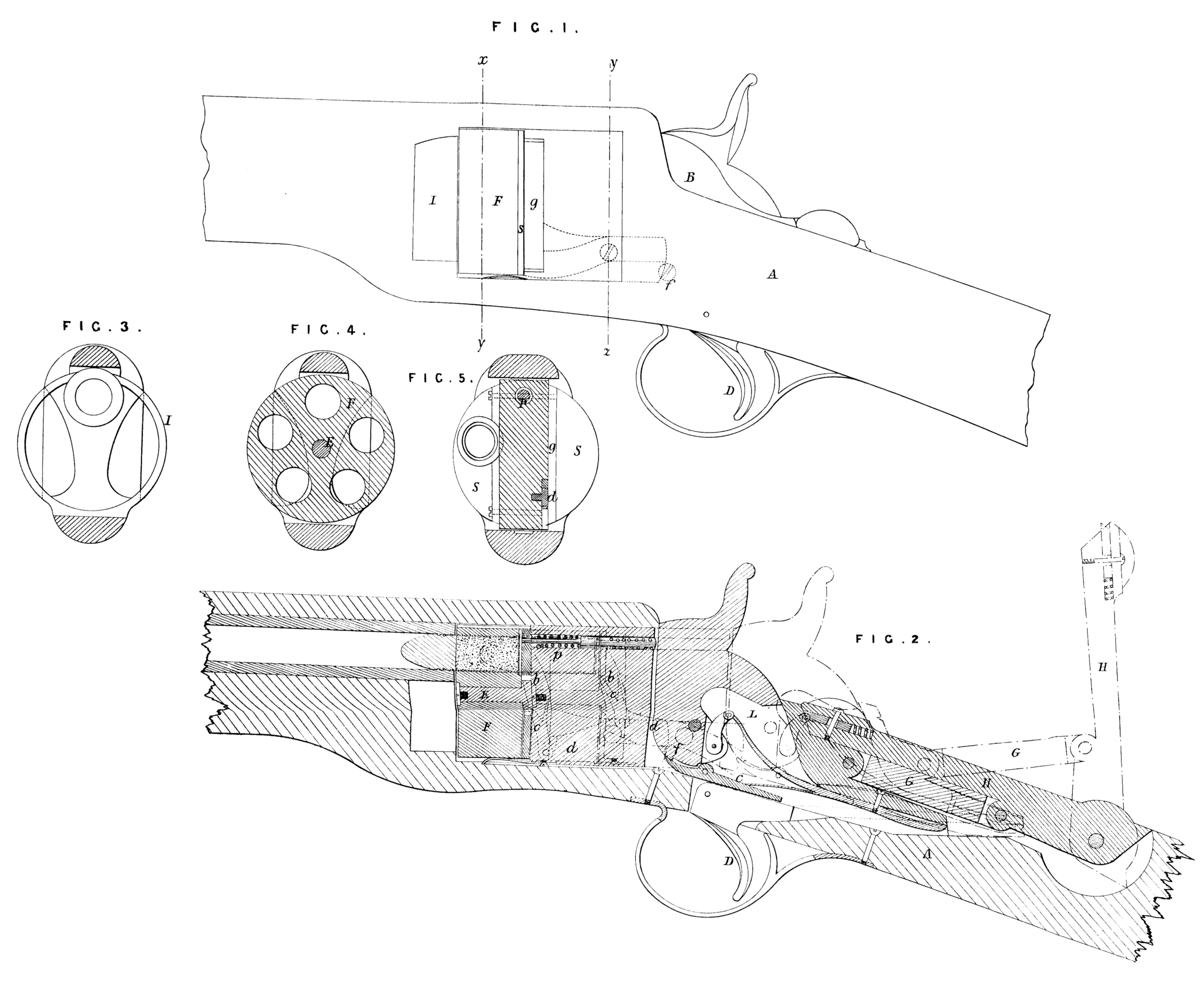
Figure 1 of the annexed Sheet of Drawings is a side elevation of that part of a repeating rifle which embodies some of the present improvements; Figure 2 represents a corresponding longitudinal section of the same according to a vertical plane passing through the axis of the barrel, the black lines in this Figure indicating the breech closed against the butt of the barrel, while the red lines represent it open; Figures 3 and 4 are transverse sections of the same, at the line #, y, of Figure 1 *and looking towards the barrel; in the former Figure the breech is supposed to be removed, in the latter it is closed ; Figure 5 represents a transverse section of the same at the line y, z, of Figure 1, also working towards the barrel; Figure 6 is a side elevation of a portion of a breech-loading carbine embodying some of these improvements; Figure 7 represents a sectional elevation of the same, the section being made by a vertical plane passing through the axis of the barrel; Figure 8 is a top view of the same; Figure 9 represents a side elevation of a breech-loading pistol embodying some of these improvements, and showing the breech in its extreme position, that is, when closed and when open, in black and red lines respectively ; Figure 10 is a section of the same according to a vertical plane passing through the axis of the barrel; and Figures 11 and 12 are transverse sections at the line y, of Figure 9, the former looking towards the barrel, the latter towards the stock.
The fire-arm represented in Figures 1, 2, 3, 4, and 5 is a repeating fire-arm, having a revolving cylinder whose length is shorter than the length of the cartridge case (so that the front end of a cartridge when in a chamber of the cylinder protrudes in front of it); this cylinder is combined with the barrel by means of mechanism in such manner that the cylinder is withdrawn from the butt of the barrel prior to its rotation sufficiently to permit the end of the cartridge to turn, and is moved towards the barrel to close the breech and insert the protruding end of the cartridge into the butt of the barrel. By this combination the front end of the cartridge case is caused to overlap the joint of the breech at the time the charge is fired to prevent the escape thereat of any matter from within. In this instance the stock A is recessed in its upper portion to receive within its cavity the lock L, snugly encased in a casing B, open on its under side, so that the sear C of the lock may be operated upon by the trigger D, and closed at the sides and on the top, allowing only the cock of the hammer to protrude therefrom, so that the hammer may from without be cocked, and its action otherwise controlled. This casing B extends in front of the lock the length of the path which the lock in its motion to and from the barrel describes, and is fitted into a portion of the stock which is recessed at the sides, constituting a guide bolt, whereby the lock and the cylinder are guided iq their reciprocating movement. This lock case or guide bolt is therefore guided on the top and bottom by both that portion of the stock which is recessed upon its sides and that which is recessed on the top in the direction of its depth. To the front end of this casing is fixed a spindle E, upon which is mounted the revolving cylinder F, the recess from side to side in the stock being sufficiently large to admit of the cylinder having within it its reciprocating and rotary motion. To the rear end of the casing there is pivoted the link G, by means of which the casing is connected with the lever H, whose rear end is pivoted in the extreme rear end of the recess in the top of the stock, and the dimensions of the parts are such that when the lever is raised, as shown in red lines in Figure 2, the revolving cylinder and lock are moved back from the butt of the barrel, leaving ample space between the front end of the cylinder and the barrel for the projecting ends of the cartridges to turn into line with the barrel without sticking. By depressing the lever the cylinder is brought in contact with the barrel, its uppermost chamber being in line therewith, while the lock is brought in such relative position to the trigger in the stock as that the sear in the lock is in juxtaposition therewith, and ready to be operated upon by the trigger. The front ends of the cartridges that project from the cylinder are protected against injury by a guard ring I, secured to the stock beneath the barrel, which is designed to receive the ends of the cartridges when the breech is closed by the forward movement of the cylinder. In order to revolve the cylinder a ratchet wheel b is fitted to the rear or butt of the cylinder; the teeth of this ratchet wheel are operated upon by a spring pall c, which is pivoted to one arm of a vibrating pawl d, pivoted in its turn to the outside of the lock case, and deriving its vibratory motion from a pin or stud/, fixed to and projecting from the interior face of the recess of the stock. The vibratory pall is so shaped as to be operated by the pin or stud during that part of the backward movement of the cylinder and its appurtenances when the ends of the cartridges are clear of the barrel. Before the cylinder reaches its most backward position* the incline or cam side of the vibratory pall comes in contact with the pin, so that the continued movement of the cylinder by the lever causes the pall lever to vibrate and to rotate the cylinder. This rotation of the cylinder continues until the chamber previously in line with the barrel is moved past it, and a succeeding chamber is brought into line with the barrel. When this is accomplished the further rotation of the cylinder and its further movement backward by the lever are simultaneously stopped by the projecting end g of the shield s coming in contact with the bottom of the side recess in the stock. The rear end of the vibratory pall is now in such a position that when the cylinder is moved forwards by the lever H, the pin f comes in contact with the rear end of the vibratory pall sufficiently before the cylinder reaches its place at the butt of the barrel to move the pall lever the distance required to withdraw the pall from the ratchet tooth with which it was in contact, and engage it with the tooth appertaining to the succeeding chamber of the cylinder. In order to transmit the blow from the hammer through the intermediate lock case of the guide bolt to the cartridge, I provide the said lock case with a percussion pin P, located in an orifice in the body of the lock case, in line with the percussion hammer and the flange of the cartridge to be struck. This percussion pin is caused, by means of a spiral spring, to slightly protrude from the face of the block opposite the hammer, whilst its front end is flush with the face of the case which is opposite the cylinder.
The arm shown in Figures 6, 7, and 8 is provided with a sliding breech pin A, sliding in a recess in the stock, and moving together with the lock, while the stock remains permanently with the barrel. The breech pin is hollow, and contains within its cavity the various parts constituting a lock, the hammer B, however, being allowed to project through a slot in the top of the breech pin, and to rest on the breech block in a recess provided in the top thereof. In this recess upon one side of the hammer there is pivoted a hook D, whose function it is to take hold of the flange of the butt of the cartridge. For this purpose the hook is made of thin sheet metal, and with its front edge fitting in a recess in the barrel, and curved in the fashion of a cam, it is pivoted to one side in the slot by means of a friction joint, so that the hook remains in any position it may be given. This hook or jaw is located within the slot of the breech pin, and protrudes at the front thereof, so as to lap over the uppermost portion of the flange of the cartridge. The front of the breech pin is recessed the depth of the thickness of the flange of the cartridge, and forms the seat thereof. At the side of the hook the hammer is recessed, or so constructed as not to come in side contact with the hook, but to form a shoulder which, when the hammer is let down on the breech block, bears on the hook, and causes it to grasp the flange of the cartridge.
The operation of this device is as follows:—To load the arm the breech is opened by raising the lever P, which, by means of an intermediate link L, is connected with the breech pin, as shown in the annexed Drawings. The breech pin being thus withdrawn, the cartridge is inserted into the barrel, leaving the flange thereof on the outside at the butt of the barrel; the breech is now closed by depressing the lever P, and the butt of the cartridge will be snugly housed in the recess provided therefor. The hammer during these operations is supposed to be at half cock, and the hook raised above the line of the cartridge; when the gun or pistol is to be fired it is first brought to a full cock, and released by the action of the trigger. The hammer thus suddenly let down on the cartridge flange not only explodes the percussion powder it contains, but carries in its descent the hook with it, and causes it to lock in with the flange of the cartridge, and to keep so locked by the pressure exerted upon it by the shoulder of the trigger as well as by virtue of the friction pivot by which it is attached to the breech block, and whereby its position is unalterably maintained until removed therefrom. If the breech be closed without having the hammer and hook raised, then the hook will be carried over the flange of the cartridge by its own cam-shaped nose, and will be depressed when past the flange by the spring actuating the hammer. From this it will be readily understood that if the breech be opened while the hammer is down, and whether the cartridge shall have been fired or not, it will withdraw the cartridge, and hold it within the recessed breech block in line with the barrel. From the above it will also be understood that after the hook is once depressed on to the cartridge it will remain in position without the aid of the hammer; the cartridge will therefore remain connected with the breech block in any position thereof relatively to the barrel, although the hammer at the same time be cocked. The cartridge or its case may be removed by hand and another placed in its stead on the breech pin, or preferably inserted in the barrel. The breech pin is guided’in its movement to and from the butt of the barrel by a guide bolt fast to or made in one piece with the breech pin, and sliding in a recess provided in the stock under the barrel. This guide bolt, shown in the accompanying Drawings, is square in its cross section and hollow, a cavity being formed underneath, within which cavity is arranged the mainspring, its one end being riveted or otherwise secured to the forward end of the bolt, while its other end is connected by a link with the tumbler. By this arrangement of reverso spring the breech pin may be constructed more compactly than this could be done if the spring were placed as usual in the rear of the hammer, and allows the use of (for this class of fire-arms) comparatively short stocks.
Figures 9, 10, 11, and 12 in the accompanying Drawings represent that portion of a pistol which embodies some of these improvements. A is the stock of the pistol. Externally it is shaped like most pistols, the stock or hilt being curved downward ns it recedes from the barrel, augmenting in thickness so as to afford easy grasp by the hand. The stock or handle is recessed on the top to a sufficient depth to contain a sliding breech pin, with which are connected its appurtenances, consisting of the lock hammer, moveable jaws, and a mechanism for opening and closing the breech. The breech pin B is recessed in front to contain and fit within it the butt of the flanged cartridge when the breech is closed. It is hollow in the rear, containing within its cavity part of the hammer, with its actuating mainspring C, tumbler T, sear D, and sear spring E, also a hook or jaw F, hung upon a transverse pin a. This hook projects out of the face of the breech pin, and is provided with a tail piece h, which is arranged in relation to and actuated by the hammer or a cam on the hammer G in such a manner that when the hammer is let down the hook is pressed out and held in position, performing the function of a fixed jaw supporting the cartridge by its flange ; but when the hammer is raised or cocked the pressure on the tail piece b is removed, and the hook is free to recede or swiog back on its suspension pin according to its gravity. Thus, if the breech pin be withdrawn, the hammer half cocked to throw off the case of the exploded cartridge, and a new cartridge inserted in the barrel, and if the breech bo then closed, the operation attending the last movement would be as follows :—As the breech pin closes against the butt of the barrel the protruding portion of the hook comes in contact with the butt of the cartridge. The hook at this moment is free to recede, and being suspended on a traverse pin situate in line of the axis of the breech, or thereabouts, the hook will in receding describe an arc of a circle, aud thus clear the flange of the cartridge. When the breech is brought home and closed, the flanged butt of the cartridge will snugly fit the recessed front of the breech pin, the pistol is loaded and ready to be fired at any time, the hammer for this purpose is placed to full cock and released in the usual manner by pulling the trigger. The hammer in striking the flange of the cartridge presses on the tail piece b, and moves the hook up to clasp the flange of the cartridge. The cartridge is now firmly held in the recessed breech pin b)vthe hook and the beak of the hammer, the latter both maintaining the hook and pressing the cartridge down on to the said hook. If the breech pin be now withdrawn, the cartridge, whether exploded or not, will also be withdrawn from the barrel. From this it will be understood that it is not necessary to fire the cartridge in order to withdraw it, for if the hammer be let down gently it will grasp the cartridge without indenting the flange, and consequently without exploding its contents. To allow of the withdrawal of a cylindrical cartridge case from a cylindrical barrel, when the breech pin moves out of line of the axis in a curvilinear path, the hammer is provided with a beak c, sufficiently extended to permit the cartridge case to move on the jaw as a center of rotation without coming out of contact therewith. ‘This beak may have its under surface placed concentrically with the jaw, or the hammer may be caused to bear with a yielding pressure on the flange, so as to adjust itself to the different positions of the cartridge case in relation thereto. The breech pin, with its appurtenances, is moved in the recess of the stock by means of a lever H, which is connected with the breech pin by a link I. When depressed, the lever II is firmly held in place by a spring catch l£, which is operated by a button or otherwise to release its hold. The breech pin is properly guided in its motion to and from the butt of the barrel by a curved guide bar L, fast to the front end of the breech pin, and sliding in a curved slot M. A pin R is provided in order to limit the extent of the motion of the breech pin. The trigger guard S is made fast to the stock and encloses the trigger V, so that but so much of it will protrude therefrom as will give it necessary play to operate the sear. The trigger is entirely disconnected from the breech pin and its appurtenances, so that the latter may be moved to and fro in the recess of the stock without moving or operating the trigger, and its arrangement in relation to the stock and the sliding breech pin and appurtenances is such that the. sear which actuates the hammer cannot be operated thereby unless the breech pin is closed. By this arrangement-the danger attending the operation of sliding breech pins when moving together with the trigger is effectually avoided.
Having now described aud particularly ascertained the nature of the said Invention, and the manner in which the same is or may be used or carried into effect, I would observe in conclusion that what I consider to be novel and original, and therefore claim as the Invention secured to me by the herein-before in part recited Letters Patent, is,—
1st, the general constructions and arrangements of breech-loading fire-arms, as herein-before described and illustrated by the Drawings.
2nd, the combination of a cylinder shorter than the length of the cartridge case used therein,^and having, when operated, a compound back and forth and rotary motion, and a lock in such manner that th$se two move together in a recess or recesses in the stock, whilst the stock remains permanently connected with the barrel of the fire-arm, substantially as herein-beforo described.
3rd, the combination with a cylinder having a sliding and rotary motion, and back moving with the cylinder to and from the barrel in a recess in the stock, of a trigger permanently connected with the stock, the whole being arranged to operate substantially as herein-before described.
4tb, the combination with a sliding revolving cylinder sliding with the lock in a recess or recesses in the stock of a lock case of such construction that it performs the functions of guiding the cylinder and protecting the lock whilst moving to and from the barrel, substantially as herein-before described.
5 th, the combination with a sliding revolving cylinder and a lock containing guide case, when moving together in recesses in the stock to and from the barrel, of a percussion pin situate within the said case to transmit the blow of the hammer to the cartridge in the barrel, substantially as herein-before described.
6th, the combination of a lever which moves the sliding and revolving cylinder in a recess of the stock to and from the barrel and of a mechanism for operating the revolution of the cylinder, under such arrangement that when the said lever is raised on a pivot on the rear end thereof the cylinder is drawn back and in line with the barrel and rotated upon its axis, substantially as herein-before described.
7th, in breech-loading fire-arms in which a breech pin is used sliding in a recess in the stock, and moving together with the lock to and from the barrel, I claim the breech block recessed in front to receive the flanged end of the cartridge in combination with a hammer and hook, the latter being pivoted by friction joint in the breech block, and actuated by the hammer, substantially in the manner and for the purposes herein-before described.
8th, in breech-loading fire-arms in which a sliding breech pin together with the lock is moved to and from the barrel by a lever and an intermediate link as described, I claim guiding the said breech pin by means of a hollow guide bolt made in one piece with or permanently attached to the said breech pin, in combination with the arrangement of the mainspring within the cavity of the bolt, substantially in the manner and for the purpose hereinbefore described.
9th, I claim the combination of a sliding breech block with a hammer and pendant hook to seize and hold the cartridge by its flanged butt, the arrangement being such that the hook is actuated by the hammer to operate in connection therewith, substantially as herein-before described.
10th, I claim the combination of a breech pin sliding to and from the barrel, but out of line of its axis, with a hook and hammer to seize and hold the cartridge by its flanged butt, the arrangement being such as to allow tho cartridge to move on the hook as a fulcrum as the breech pin recedes from or approaches to the butt of tho barrel, substantially as herein-before described.
11th, in combination with a sliding breech pin provided with hooks or their equivalent to receive and hold the cartridge, and moving together with the lock in a recess in the stock, I claim a trigger directly connected with the stock, and operating the lock only when the breech is closed, substantially as herein-before described.
In witness whereof, I, the said John Henry Johnson, have hereunto set my hand and seal, this Seventeenth day of November, One thousand eight hundred and sixty-three.