
British 2768
LETTERS PATENT to Jehiel Keeler Hoyt, of the City, County, and State of New York, United States, now of No. 12, Southampton Buildings, Chancery Lane, in the County of Middlesex, for the Invention of “ Improvements nr Revolving Fire-asms.”—A communication from abroad by Benjamin Franklyn Joslyn, of Stonington, Connecticut, United States of America.
Sealed the 8rd May 1864, and dated the 7th November 1863.
COMPLETE SPECIFICATION filed by the said Jehiel Keeler Hoyt at the Office of the Commissioners of Patents, with his Petition and Declaration, on the 7th November 1863, pursuant to the 9th Section of the Patent Law Amendment Act, 1852.
TO ALL TO WHOM THESE PRESENTS SHALL COME, I, Jehiel Keeler Hoyt, of the City, County, and State of New York, United States, now of No. 12, Southampton Buildings, Chancery Lane, in the County of Middlesex, send greeting.
WHEREAS I am in possession of an Invention for “ Improvements in Revolving Fire-arms,” and have petitioned Her Majesty to grant unto me, my executors, administrators, and assigns, Her Royal Letters Patent for the same,, and have made solemn Declaration that it has been communicated to me from abroad by Benjamin Franklyn Joslyn, of Stoniiigton, Connecticut, United States of America.
NOW KNOW YE, that I, the said Benjamin Franklyn Joslyn, do hereby declare that the following Complete Specification under my hand and seal fully describes and ascertains the nature of said Invention, and in what manner the same is to be performed, in and by the following statement, reference being had to the accompanying Drawings, making a part of this Specification.
Said Invention relates to improvements in that class of revolving fire-arms in which metallic cartridges are used.
The first part of said Invention consists, firstly, of a device for preventing the spent cartridges from interfering with the free rotation of the cylinder; secondly, of a breech plate attached to or forming a part of the frame, and so constructed with respect to the cylinder as to permit the lateral movement of the same to a limited extent from the frame, and to guide the cylinder when it has to be returned to its proper position, thereby obviating the delay incurred in detaching the cylinders of ordinary revolvers entirely from and readjusting them in the frame; thirdly, in a novel device for operating the cylinder through the movement of the hammer; fourthly, of a movable centre pin for the rear of the barrel, the movement of the pin being limited by a spring and lip on the same, as described hereafter ; fifthly, of a novel device for retaining and releasing the cylinder; and, sixthly, of a device serving the double purpose of a centre pin for the front of the cylinder and a suitable instrument for removing the spent cartridges from the chambers of the cylinder.
The second part of said Invention consists, firstly, of a mode, described hereafter, of constructing the stock and frame of a revolving fire-arm in two parts, connected together and arranged to permit a lateral movement of the cylinder, substantially as described hereafter; secondly, of a peculiar manner of constructing the rear of the cylinder; thirdly, of a modified device for retaining and releasing the cylinder; and, fourthly, of a modified device serving the double purpose of a centre pin and of an instrument for forcing the spent cartridges from the chambers of the cylinder.
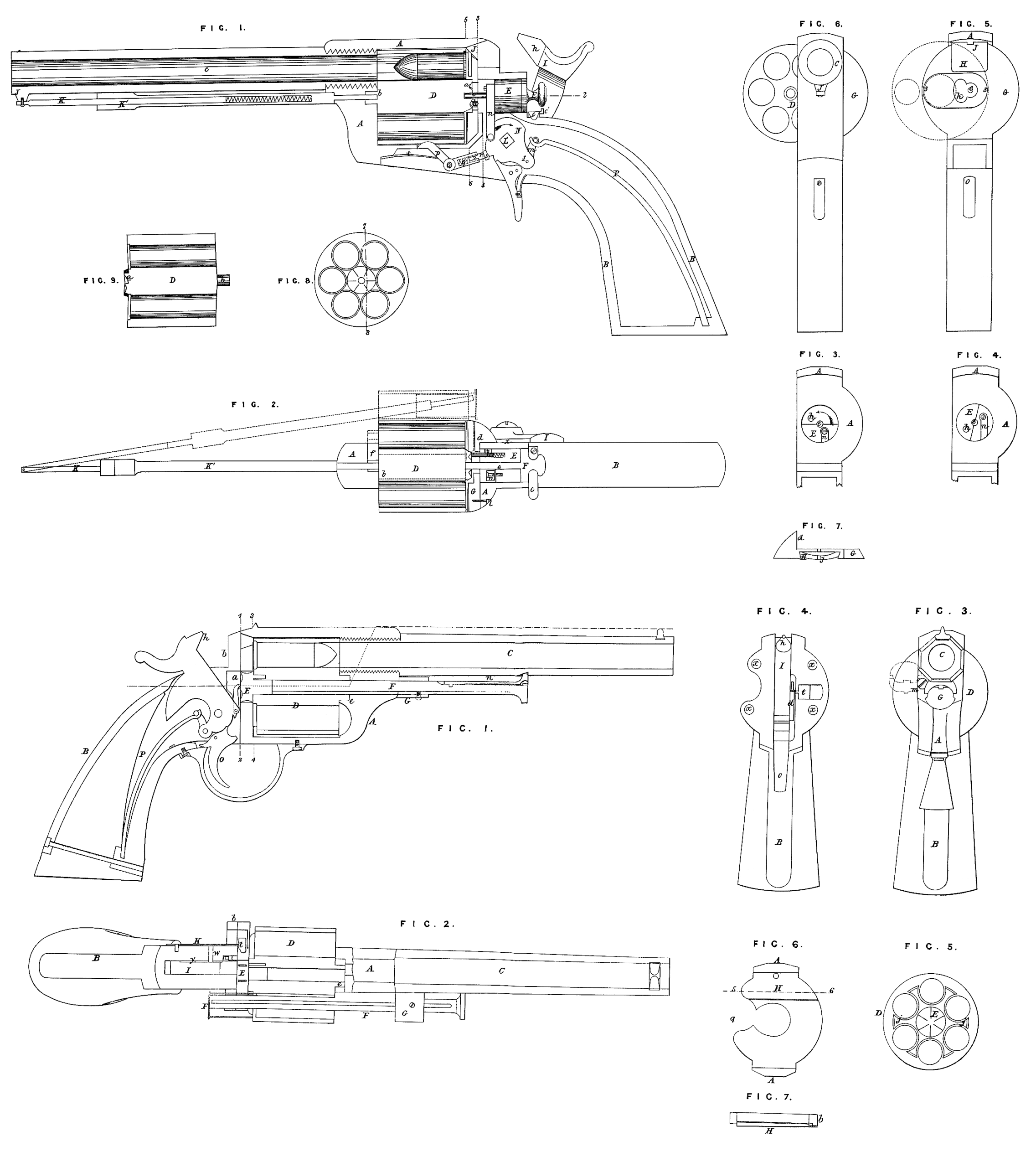
On Drawing No. 1, which relates to the first part of my Invention, Figure 1 is a longitudinal section of the improved breech-loading revolving fire-arm; Figure 2, a sectional plan on the line 1, 2, Figure 1 ; Figures 3 and 4, transverse sections on the line 3, 4, Figure 1 ; Figure 5, a transverse section on the line 5, 6, Figure 1; Figure 6, an end view ; Figure 7, a detached view of part of the fire-arm ; Figure 8, a view of the rear of the cylinder; and Figure 9, a longitudinal section of the same on the line 7, 8, Figure 8. Similar letters refers to similar parts throughout the several views.
A is the frame of the pistol, an extension B from the rear of which forms the stock or handle, the barrel C being secured to the front end of the frame in the usual manner. In the rectangular opening of the frame A revolves the cylinder D, at the rear of which is a projection a, having as many depressions as there are chambers in the cylinder, each depression being inclined on one side and abrupt on the other, as best observed on reference to the sectional view, Figure 9. On the front end of the cylinder B is a tubular projection b which is arranged to fit snugly in, and when necessary, to slide to and fro in a groove/ formed in the frame A (see Figure 2). In the frame, at the rear of the cylinder, is a circular opening in which the cylindrical block E fits snugly, and through this block passes a pin e, the end of which fits into a recess in the projection a of the cylinder, a portion of the head F of the pin fitting in the opening of the frame which contains the block, in which position the head is retained by the spring C, the latter having a lip c1, the purpose of which will appear hereafter. It will be observed, on reference to Figures 2, 3, and 4, that a portion of the front end of the block E is cut away, leaving a semi-cylindrical projection in which a longitudinal opening for the reception of the pin h> the outer end of which is so beveled as to engage properly in depressions of the projection a, a spiral spring in the opening and at the rear of the pin tending to force the latter towards the cylinder, while the pin is retained within proper limits by a projection passing into an oblong slot in the block, as seen in Figure 2. It should be understood that this block E is arranged to turn freely in the frame, but to have no longitudinal movement. Between the rear of the cylinder aud the frame intervenes a breech plate G, in which is a central opening of such shape and dimensions as to allow for the free movement of the pin e and pin h, the plate having on one side a lug d fitting against the side x of the frame, to which the plate is secured by a set screw l, Figure 2. In the face of the plate G is a depression, the edges of which are beveled and adapted to the beveled edges of a recoil plate H, which fits loosely in and so as to be readily withdrawn vertically from the plate G when the latter is detached from the frame. The recoil plate is so situated as to form the rear of one of the chambers of the cylinder when the front of the chamber coincides with the bore of the barrel, the face of the recoil plate being slightly convex and projecting beyond the face of the breech plate, while the inside is concave, as seen in Figure 7. The recoil plate being somewhat loose in the recess of the breech plate is capable of yielding to a limited extent at the moment the discharge of the cartridge takes place, but instantly recovers its former position after the discharge. In the upper edge of the recoil plate is cut a notch j, through which passes the point k of the hammer I as it falls upon the edge of the flange or enlargement of the metallic cartridges used in connection with the improvements. On the hammer pin L is secured a cam-shaped lever N having the usual notches, in which engages the upper end of the trigger 0, the main spring P being connected to the arm sl of this lever by a link m. From the face of the lever N projects a pin, to which is connected the lower end of the connecting rod n, the upper end of the latter being jointed to a pin on that part of the block from which, as before remarked, a portion is cut away. To a spindle Q attached to the frame below the cylinder is hinged a lever having two arms/? and q, the latter having an orifice for the reception of the sliding rod r, the head s of which is pressed against the edge of the cam-shaped lever N by a spiral spring contained in the said orifice. A flat spring t is secured at one end to the under side of the frame, the other end bearing against the under side of the army?, the rounded portion of which is arranged to fit in a slight depression formed in the cylinder at such points that when the end of the arm is in one of the said depressions one of the chambers of the cylinder must coincide with the bore of the barrel. To a projection J beneath the barrel and near the muzzle, one end of a rod K is so jointed that it can be moved laterally, the rod fitting snugly, but so as to slide freely in the tubular rod K\ the rear end of which passes through the frame A and into the tubular projection b of the cylinder, thus forming the pin on which the front end of the said cylinder revolves. A spiral spring contained within the tubular rod K1, and bearing against the rod K, tends to maintain both rods in their proper position when not required for the use explained hereafter. On cocking the hammer the lever N will turn in the direction of its arrow, and through the connecting rod n cause the cylindrical block E (which, while the hammer was down, occupied the position shown in Figure 3) to turn in the direction of its arrow. As the lever N turns the friction between its edge and the head of the pin r causes the arm q to be elevated, and the arm p consequently depressed, free from the depressions in the cylinder, thereby causing the latter to be released. The pin h, owing to the movement imparted to it by the partial turning of the block E, will, as it bears against the abrupt side of one of the depressions in the projection a of the cylinder, move the latter round to an extent sufficient to bring into a line with the bore of the barrel that chamber of the cylinder next to that which had, prior to the movement of the cylinder, coincided with the said bore. When the hammer has been brought to the position of full cock the arm q is released and the spring t forces the arm p against the cylinder, the head of the arm entering one of the depressions, so that the cylinder is retained in a proper position prior to the falling of the hammer, and will remain in that position daring the descent of the hammer and until the latter is again moved back. On releasing the hammer the lever N is turned by the action of the springy? in the direction contrary to that pointed out by the arrow, the hammer striking the edge of the flange of the cartridge and discharging the contents of the same. During this movement of the lever the block E is turned back to its former position, the pin e sliding over the inclined side of the depression in the projection a of the cylinder takes its place in the adjacent depression « preparatory to a repetition of the above-described movements.
In fire-arms of the class to which the improvements relate the free turning of the cylinder is obstructed to a greater or less degree owing to the heads of the cartridges being forced by the explosion of the contents back against the breech plate, thereby causing an undue friction, which has been the great objection to the use of metallic cartridges in revolving fire-arms. The main object in my present improvements has been to overcome this difficulty. It should be understood that the heads of the cartridges in the cylinder prior to their discharge come successively in contact, but only just in contact, with the convex face of the recoil plate H, so that no undue force is required in revolving the cylinder and transferring the heads of the cartridges in succession to a position coinciding with the recoil plate, as little force is required in the improvements to move the head of a spent cartridge from the recoil plate for the following reasons:—The moment the discharge takes place the spent cartridge is forced with a violent concussion against the recoil plate, and the latter yields slightly to the force of the shock. The instant the latter is expended, however, the plate, owing to its elasticity, recovers its former position, pushes back and compresses the head of the cartridge so that it is either clear of the plate or bears so lightly against the same as to present no obstruction to the free turning of the cylinder. When the empty cartridge cases have to be discharged from the chambers preparatory to reloading, the hammer is brought to half-cock, the spring c is depressed below the edge of the head F of the pin e, and the latter is withdrawn until arrested by th^ lip c1 of the spring, which prevents its further outward movement. The tubular rod K1 is then pushed forward until its end is released from the projection b of the cylinder as well as from the frame, when, by a lateral movement of the cylinder, which is now free from the pins on which it has turned, it may be thrown out to the position shown in Figures 5 and 6, the projection b passing along the groove f of the frame, the projection a moving in the oblong slot in the breech plate until it strikes the edge z, Figure 5, which prevents any further outward movement of the Cylinder. The rods K and Kl are then turned to one side and the rod Kl drawn back, so that its end may enter one of the chambers of
the cylinder and the empty cartridge case and be used as an instrument for pushing the latter from the chamber (see Figure 2). After a case has been discharged from one chamber the cylinder is turned by the finger and thumb until the adjacent chamber with its empty case is brought in a position to be treated in a like manner; and after all the cases have been removed the cylinder is reloaded and pushed back to its place, the pin e being moved into the orifice of the projection a, and the end of the rod Kl into the orifice of the projection 1, when the fire-arm is in a condition to be again discharged.
As there is no necessity for disconnecting the cylinder entirely from the fire-arm for the purpose of loading or of withdrawing the spent cartridges, and as the cylinder when moved out laterally is self-adjusting to its proper place, a slight lateral push being all that is necessary for the purpose, it will be evident that this portion of the improvements prevents the delay experienced in handling and adjusting the detachable cylinders and breech-pieces of ordinary revolving fire-arms. It will also be seen that the devices for revolving the cylinder are simple and efficacious, and not of a character to be damaged or easily disarranged. The pin e cannot be lost or mislaid owing to the spring c which can be depressed sufficiently to allow for the withdrawal of the pin from the orifice in the cylinder, the lip c, however, preventing its further withdrawal. The rod K and tubular rod K1 have the advantage of forming a suitable instrument, always at hand, for discharging the spent cartridges from the chambers of the cylinder, the end of the rod K1 at the same time forming a detachable pin, on which the front end of the cylinder turns.
On Drawing No. 2, which forms the second part of my Invention, Figure 1 is a longitudinal section, illustrating a modification of the improved revolving fire-arms ; Figure 2, a plan view partly in section ; Figure 3, an end view; Figure 4, a transverse section on the line 1, 2, Figure 1, the barrel and frame being removed; Figure 5, an end view of the cylinder; Figure 6, a transverse section on the line 3, 4, Figure 1 ; and Figure 7, a section on the line 5, 6, Figure 6. Similar letters refer to similar parts throughout the several views.
A represents the frame; B, the stock; C, the barrel; and D, the cylinder of the fire-arm. In the present instance the stock and frame are not made in one piece, as described in reference to Drawing No. 1, but are secured to each other at the point designated by the line 1, 2, Figure 1, by suitable set screws passing through holes x in the flange b of the stock, and screwing into the frame. The hammer I, link m, main spring P, trigger o, and dog d, are connected to the stock B, and are too similar to those of ordinary revolving fire-arms to need a minute description. The cylinder D has at its front end a
projection e9 adapted to a recess in the frame, of such a form as to permit the cylinder to move laterally in the manner described above, and into the front end of the cylinder is fitted a projection on the block £, which cannot turn independently of the cylinder owing to a pin /. An opening i, Figure 6, is formed in the rear of the frame for the reception of the block E, the opening being of such a form as to permit the free rotation of the block as well as a limited lateral movement. On the rear of the block are formed suitable teeth so arranged in respect to the dog d that on cocking the hammer the cylinder will be turned to the proper extent. A rod F, passing through the frame beneath the barrel into the cylinder, serves as ‘the centre pin on which the cylinder revolves, the rod being arrauged to slide freely in an arm G, which is hung loosely to the frame at m, Figure 3, and the end of the rod being furnished with a spring n, the outer end of which fitting in a depression on the under side of the barrel, serves to maintain the rod in its proper position in respect to the cylinder. The rear end of the cylinder has a series of projections jf Figure 5, of such a shape as to form around each chamber a recess for the reception of the head of the metallio cartridge, the projections bearing lightly against a breech-plate H, secured to the inside of the frame, as seen in Figure 6. This plate may be arranged to yield and recoil when the discharge of one of the cartridges takes place, in the same manner and for the same purpose as that described in reference to the plate H in Drawing No. 1. On the edge of the block E, at the rear of the cylinder, are as many depressions as the cylinder has chambers, and into these depressions engages a projection t on the end of a spring K, which is secured to the side of the stock, the tendency of the spring being to maintain a portion of the projection t in one or other of the said depressions (see Figure 2). A small pin w passes through and is arranged to slide in the stock, one end of the pin being in contact with the spring, and the other end in contact with the side of the hammer on which an inclined projection y, Figure 2, is formed, the latter on elevating the hammer bearing against the pin w9 and thereby forcing the spring outwards, and moving its head or projection t clear of the depressions in the edge of the block E. It should be understood that the inclined projection on the side of the hammer is so formed and arranged as to cause the spring K to release the cylinder during such time only as the dog d is in the act of revolving the cylinder; at all other times the latter is locked by the spring and its projection t. It will be seen that on withdrawing the rod or centre pin F from the cylinder the latter is at liberty to be moved laterally to an extent sufficient to allow for the introduction of the metallio cartridges into the chambers* the flange 6 of the stock* as well as the flange of the frame to which that of the stock is secured, being so cut away at q, Figures 4 and 6, as to permit the insertion of the cartridges after a much less lateral movement of the cylinder than that described in Drawing No. 1. When the spent cartridges have to be removed from the chamber, the rod F is withdrawn from the cylinder, and clear of the frame, the cylinder is moved laterally from the frame, and the arm G is turned away from the barrel, and the rod F thereby brought into a proper position to be used as an instrument for forcing the spent cartridges from the chamber. When the cylinder has to be detached, which is rarely required, the stock is unscrewed from the frame, after which the block E can be driven from the cylinder by the rod F, when the cylinder is at liberty.
Having thus fully described my Invention, and shown in what manner the same may be conveniently and advantageously carried into effect, I claim,—
Firstly, in connection with revolving fire-arms arranged for the use of metallic cartridges, a recoil plate (Drawing No. 1) on the frame or on a breech-plate attached to the frame, said recoil plate being situated at the rear of the cartridge when the latter is in position to be discharged, and operating so as to permit the free turning of the cylinder, as herein described.
Secondly, the breech-plate G so constructed and arranged in respect to the cylinder, that it shall permit a limited movement of the cylinder laterally from the frame, and shall serve as a guide on restoring the cylinder to its proper position preparatory to the discharge of the cartridge, substantially in the manner set forth for the purpose specified.
Thirdly, the block E (Drawing No. 1) arranged to turn in the frame on the movement of the hammer, and having a yielding pin h adapted to the recesses in the rear of the cylinder, the whole being arranged and operating substantially as and for the purpose herein set forth.
Fourthly, the combination of the sliding pin e and its head F, spring c and its lip cl (Drawing No. 1), the whole being constructed and arranged in respect to the cylinder substantially as specified.
Fifthly, in combination with the cam-shaped lever L I claim the lever with its two arms p and q, yielding rod r, and spring £, or its equivalent, the whole beiug arranged and operating for the retention and release of the cylinder, substantially as specified and illustrated in Drawing No. 1.
Sixthly, the rod K and tubular rod K1 with its spring, the whole being connected to the barrel substantially as described, and arranged to serve the double purpose of a centre pin for the cylinder and an instrument for discharging the spent cartridges.
Seventhly, constructing the stock and ffame of the fire-arm of two parts secured together and arranged to permit a lateral movement of the cylinder, substantially as described and illustrated in Drawing No. 2.
Eighthly, the block E, adapted to and rendered detachable from the cylinder substantially as set forth, and having teeth at the rear, and depressions on the edge for the purpose specified (Drawing No. 2).
Ninthly, the spring K with its head t when combined with the hammer and cylinder, and operating to lock and release the latter on moving the hammer, substantially as set forth, and shown in Drawing No. 2.
Tenthly, the rod F and arm G (Drawing No. 2) arranged substantially as set forth, so as to serve as a centre pin and as an instrument for forcing the spent cartridges from the chamber of the cylinder.
In witness whereof, I, the said Jehiel Keeler Hoyt, have hereunto set my hand and seal, this Fifth day of November, in the year of our Lord One thousand eight hundred and sixty-three.
JEHIEL KEELER HOYT. (l.s.)
Witness,
George Haseltine,
International Patent Office,
12, Southampton Buildings,
Chancery Lane, London.