
British 2250
LETTERS PATENT to William Clark, of 53, Chancery Lane, in the County of Middlesex, Engineer and Patent Agent, for the Invention of “ Improvements in Revolving Fire-arms.”—A communication from abroad by Thomas Jefferson Vail, of Hartford, County of Hartford, and State of Connecticut, United States of America.
Sealed the 5th February 1864, and dated the 12th September 1863.
PROVISIONAL SPECIFICATION left by the said William Clark at the Office of the Commissioners of Patents, with his Petition, on the 12th September 1863.
1, William Clark, of 53, Chancery Lane, in the County of Middlesex, Engineer and Patent Agent, do hereby declare the nature of the said Invention for “ Improvements in Revolving Fire-arms,” to be as follows:—
The nature of this Invention consists, firstly, in the employment in combination with a cylinder frame opening by a movement on a hinge joint arranged in front of and below the axis of the cylinder, and with an axis pin secured to the barrel of a spring latch, so constructed and applied as to serve the two purposes of connecting and locking the barrel with the upper part of the frame, and of securing the rotating cylinder upon the axis pin when the barrel is disconnected from the upper part of the frame. With reference to locking the barrel to the upper part of the frame, I make the barrel with a tail piece extending rearwards, to which the spring latch above mentioned is fitted, the rear end of said latch is provided with indentations or holes for receiving suitable projections on the upper part of the back of the frame, and so connecting the barrel with that part of the frame that it may be easily disconnected by pressing up the rear end of the spring latch. To secure the rotating cylinder to the axis pin when the barrel is disconnected I make a shoulder on the under side of the latch deep enough to lap over the rear end of the cylinder, and sufficient to retain the latter in position on its axis pin whatever may be the position of the barrel.
The Invention consists, secondly, in so constructing the spring latch and the hammer that when the hammer is down it aids in securing the spring latch in its connection with the frame, and so aids in securely locking the barrel to the upper part of the frame. For this purpose there is an opening made in the rear end of the spring latch through which the hammer strikes to fire the charges, on opposite sides of which opening there are recessed shoulders to receive catches of hooked form on the hammer, so that when the hammer is down it may assist in locking or fastening the spring latch and with it the barrel in connection with the frame. Or instead of the hammer being made Vrith catches or hooks and the spring latch being furnished with shoulders as described, the hammer may have its nose tapered in a downward direction, the spring latch have a corresponding downward taper, the nose of the hammer fitting snugly in the taper opening when down, will lock the spring : latch with the same result as is produced by the catches and recessed shoulders above described.*
The Invention consists, thirdly, in so constructing the axis pin and applying the same in combination with the barrel or frame of the arm, that while remaining attached to the barrel or frame it may be employed to expel from the chambers of the cylinder the cartridge cases or shells or other matter which may remain therein after firing the arm. For this purpose said axis pin is made of nearly the same diameter as the chambers, and on the cylinder being removed from its axis pin, the latter is introduced into said chambers, and so forces out the discharged shells or cartridge cases, the barrel to which said axis is rigidly attached serving as a hand hold in this operation.
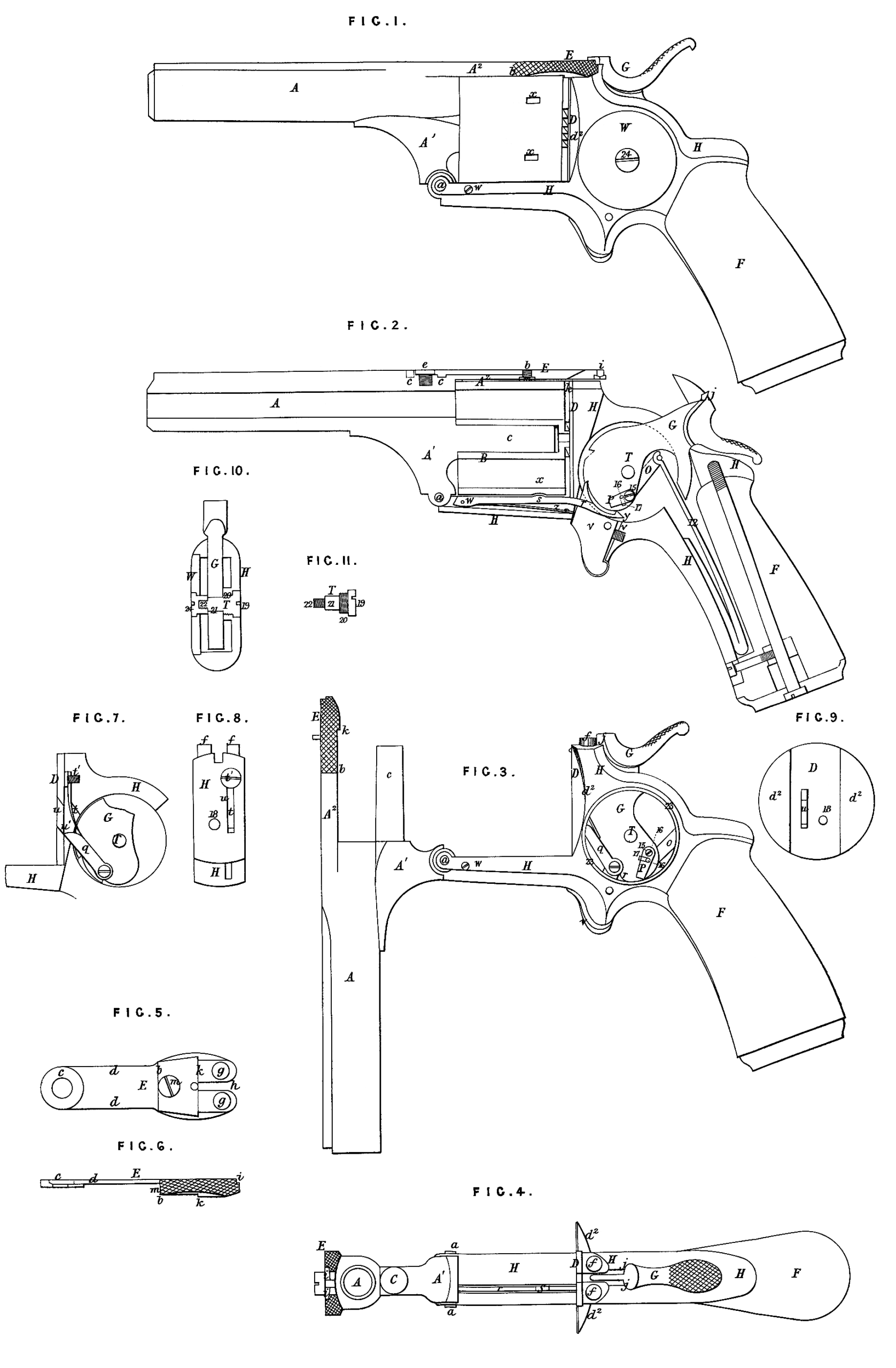
The Invention consists, fourthly, in a certain mode of applying a detachable recoil plate in combination with the spring, which keeps the revolving dog or pawl to its work, whereby the said plate, while allowing the dog to work through it, is made to aid the spring in excluding from the lock any gases escaping at the < rear of the cylinder in firing, which result may be attained by arranging the spring behind the recoil plate and in front of that part of the frame supporting said plate. The Invention consists, fifthly, in applying what may be termed a dog or pawl in connection with the tumbler of the hammer or lock, and in combination *with the locking lever for the purpose of unlocking the rotating cylinder just before the hammer is required to commence acting upon it to produce its revolution* whereby the locking lever is prevented from being unlocked or interfered with during the fall of the hammer in firing. The Invention consists, finally, in an improved construction of and mode of Applying the hammer pin, and of securing the cap plate of the lock, whereby provision is made for opening the lock without disturbing the hammer pin or •displacing any of the parts of the lock. For this purpose the pin is furnished with screw threads of different diameters with a central cylindrical part on which the hammer is mounted; this screw takes into the right side of the frame, the cap or movable side plate of the lock being on the left side, and secured by a nut taking on to the smaller screw end of the hammer pin, which remains a fixture. In this manner the cap plate can be removed without disturbing the pin, and so opening the lock. . SPECIFICATION in pursuance of the conditions of the Letters Patent, filed by the said William Clark in the Great Seal Patent Office on the 12th March 1864. TO ALL TO WHOM THESE PRESENTS SHALL COME, I, William ClAbk; of 53, Ch&ncery Lane, in the County of Middlesex, Engineer and Patent Agent, send greeting. WHEREAS Her most Excellent Majesty Queen Victoria, by Her Letters Patent, bearing date the Twelfth day of September, in the year of our Lord thousand eight hundred and sixty-three* in the twenty-seventh year of Het reign, did, for Herself, Her heirs and successors, give and grant unto me, the said William Clark, Her special licence that I, the said William Clark, iny executors, administrators, and assigns, or such others as I, the said William Clark, my executors, administrators, and assigns, should at any time agreo with, and no others, from time to time and at all times thereafter during the term therein expressed, should and lawfully might make, use, exercise, and vend, within the United Kingdom of GreSt Britain and Ireland, the Channel Islands, and Isle of Man, an Invention for “ Impbovements in Revolving Fibe-abms,* a com11 to me from abroad by Thomas Jefferson Vail, of Hartford, County of Hartford, and State of Connecticut, United States of America, upon the condition (amongst others) that I, the said William Clark, my executors or administrators, by an instrument in writing under my, or their, or one of their hands and seals, should particularly describe and ascertain the nature of the said Invention, and in what manner the same was to be per” formed, and cause the same to be filed in the Great Seal Patent Office within six calendar months next and immediately after the date of the said Letters Patent. NOW KNOW YE, that I, the said William Clark, do hereby declare the nature of the said Invention, and in what manner the same is to be performed, to be particularly described and ascertained in and by the following statement, reference being had to the Sheet of Drawings hereunto annexed, and to the letters and figures marked thereon (that is to say):— The nature of this Invention consists, firstly, in the employment in combir ' nation with a cylinder frame opening by "a movement on a hinge joint arranged in frpnt of and below the line of the axis of the cylinder, and with an axis pin secured to the barrel of a spring latch so constructed and applied as to serve the two purposes of connecting and locking the barrel with the upper part of the frame, and of securing the rotating cylinder upon the axis pin when the barrel is disconnected from the upper part of the frame. It consists, secondly, in so constructing the spring latch and the hammer that when the hammer is down it aids in securing the spring latch in its connection with the frame, and so aids in securely locking the barrel to the upper part of the frame. . It consists, thirdly, in so constructing the axis pin, and applying the same in combination with the barrel or frame of the arm, that while remaining attached to the barrel or frame it may be employed to expel from the chambers of the cylinder the cartridge cases or shells or other matter which may remain therein after firing the arm. It consists, fourthly, in a certain mode of applying a detachable recoil plate in combination with the spring which keeps the revolving dog to its work, whereby the said plate, while allowing the dog to work through it, is made to aid the said spring in excluding from the lock any gases escaping at the rear of the cylinder in firing. It consists, fifthly, in a novel mode of applying what may be termed a“ fly " or a swinging dog in connection with the tumbler of the hammer or lock, and in combination with the locking lever for the purpose of unlocking the*rotating cylinder, just before the hammer is required to commence acting upon it to produce its revolution, whereby the locking lever is prevented from being unlocked or interfered with-during the fall of the hammer1 in firing. It consists, finally, in an improved construction of and mode of applying the hammer pin and of securing the cap plate of the lock, whereby provision is made for opening the lock without disturbing the hammer pin or displacing any of the parts of the lock. In the accompanying Drawing Fig. 1 is a side view of a pistol, constructed according to this Invention, representing it in condition for use; Fig. 2 is a longitudinal vertical section of the same; Fig. 3 is a side view representing it with the cylinder frame open, and with the cylinder and the cap plate of the* lock removed ; Fig. 4 is a top view corresponding with Fig. 3; Fig. 5 is an under side view of the spring latch; Fig. 6 is an edge view of the same; Figs. 7, 8, 9, 10, and 11 represent some of the details of the Invention, and will be herein-after described. Similar letters and numbers of reference indicate corresponding parts in the several Figures. A is the stationary barrel, having at the bottom of its rear end a portion A1 projecting downward, and connecting by a hinge joint a with the lower portion of the frame H, the centre of such joint being below the axis of the cylinder, and on a line or nearly so with the lower line of the periphery of the rotating cylinder B when the cylinder is upon the axis pin C, and the parts are in condition for use. From the top of the barrel a portion A* of the rear end is extended in a rearward direction in line with the upper portion of the barrel. The portion A2 extends partly over the cylinder, and its lower face is made to conform to the periphery of the cylinder. The upper surface of A2, extending partly over the rear portion of the barrel, is grooved out to form a seat for the reception of a portion of the spring latch E, and the front portion of this seat is countersunk to receive a circular projection C (Figs. 2, 5, and 6) on the front part of the under side of the spring latch. The axis pin C, upon which the cylinder rotates, is secured to the lower projecting part A1 of the barrel, parallel with the bore thereof, and the cylinder is bored centrally of a size to fit and turn freely on the said pin. The frame H is of the same general form as that of other revolving fire-arms in which the barrel is hinged to the frame in the same manner. The construction of the spring latch E, which serves to connect the barrel with the upper part of the frame in rear of the cylinder and for holding the cylinder on the axis pin, may be understood by reference to Figs. 2, 4, 5, and 6. The projection c, before mentioned, fitted to the countersink in the top of the barrel enables it to be very firmly secured to the barrel by a single screw e, which passes through this part of the said latch, and screws into a tapped hole in the barrel. From the connection of the barrel at c to the end of the part A2 of the barrel the latch is formed as shown at d, d, to occupy the groove in the upper side of the said part A2, the thickness of this part of the latch being governed by the degree of movement or spring required. At the extremity of the said part A2 of the barrel the latch is formed with a shoulder b on the under side to abut at the end of the part A2, and the thicker portion of the latch in rear of this shoulder has it* under side made concave like the under side of A2 to conform to the periphery of the cylinder 1. At a proper point farther back there is formed on the under side of the latch another shoulder k, which is deep enough to lap over the rear end of the cylinder sufficiently to retain the latter in its proper place upon the axis pin C, whether the barrel and frame are in the relative positions shown in Figs. 1 and 2, or in that shown in Fig. 3. At a proper distance back from the shoulder k the latch is provided in its under side with indentations or holes gy gy to receive suitable projections/,/, on the upper part of the back of the frame for the purpose of connecting the barrel with that part of the frame in such manner that it may be easily disconnected by pressing up the rear end of the spring latch. In the rear end of the spring latch there is an opening h through which the hammer G strikes to fire the charges in the chambers of the cylinder. On opposite sides of this opening h there are recessed shoulders iy iy to receive catches or hook-like formations^* on the hammer, so that when the hammer is down it may assist in locking or fastening the spring latch in its connection with the frame, the latch being only capable of being released from its connection with the frame by a directly upward movement, and the movement of the hammer from that position being more backward than upward. Instead of the hammer being made with catches or hook formations j, and the spring latch being made with shoulders t‘, t, as described, the hammer may have its nose tapered in a downward direction, and the opening h in the spring latch may be made with a corresponding downward taper, and the nose of the hammer fitting snugly in this taper opening when the hammer is down will lock the spring latch with the same result as is produced by the catches j and recessed shoulders t, t; m is a stop screw to regulate the motion of the spring latch and protect it from injury in use. One advantage of the spring latch constructed and applied as above described, consists in its forming a very secure connection between the upper part of the barrel and the back of the frame and recoil shield at the time of firing, and yet affords the necessary facility for turning down the barrel, as shown in Fig. 3, to bring the cylinder to a position for loading at the rear ends of the chambers with what is known as fixed ammunition, that is to say, cartridges having metallic cases containing their own fulminate priming, or to permit the removal of the cylinder from the arm for any purpose ; and another advantage is that when the barrel has been disconnected from the upper part of the frame, the said latch still retains the cylinder on the axis pin until it is desired to remove it, when it is only necessary to press up the rear end of the said latch far enough for the shoulder k to clear the rear end of the cylinder. This last-mentioned feature is of great importance in a cavalry arm. The rotary cylinder B is similar to those in use in fire-arms constructed for loading at the rear of the chambers with fixed ammunition, except that the axis or centre hole is made ap nearly like the calibre of the chambers that the axis pin C which fits the said hole may be employed to expel from the chambers the discharged shells of the fixed ammuniton, or any matter that may remain within them after firing the arm, and for that purpose the projecting or outer end of the pin is finished off square or with a sharp or nearly sharp edge or shoulder all around it. To expel the shells and other matter from the cylinder by this means it is removed from the axis pin, which is afterwards pushed into its chamber by taking hold of the barrel to which the said pin is rigidly attached, the barrel serving for a handle in this operation. The hammer G is similar to those in use except in its being provided with the catches or hook formations j, or having its nose tapering downward, as herein-before described. The recoil plate D, which is of about the same diameter as the rotating cylinder and attached to the frame II in rear thereof, is made separately from the frame, and has projections d2, d\ on its back fitting to the sides of the frame to which it is secured by a screw 18. It has an opening or slot u through which the dog q for revolving the cylinder woiks. This dog is carried by the tumbler of the hammer and operates upon a ratchet on the rear of the cylinder in the usual manner. The face or front of the said plate is finished flat and smooth. The said plate is made separately from the frame and detachable for two reasons, one of which is that a harder metal may be used for it than for the frame, and a better finish and more perfect working of the adjacent and associated parts may be obtained, and the other is that it affords greater facility for the protection of the lock from gases escaping at the- rear of the cylinder by permitting the spring t which presses the dog q forward against the ratchet to be arranged behind the recoil plate, and in front of the portion of the frame which supports the said plate, as illustrated in Figures 7, 8, and 9, of which Fig. 7 is a vertical section parallel with the length of the arm of the recoil plate, and the portion of the frame in rear of it; Fig. 8 is a transverse section of the frame taken immediately in rear of the recoil plate, and Fig. 9 is a back view of the recoil plate. This spring t works in a slot ul in the frame H, through which the dog q also works, the said slot being of the same width as the slots u in the recoil plate, and the dog and the spring fitting as snugly in the slots u and u1 as is consistent with their proper freedom of operation. The upper part of the slot u1 is made of a form to serve as a bearing, against which the spring is secured by a screw t1 which screws into the frame H, and whose head is countersunk thereinto so that it may be covered by the recoil plate, as shown in Fig. 7. The slot u in the recoil plate is thus enabled to be made shorter than the slot ul in the frame, and the plate is thus made to cover a portion of the latter slot, and in a measure to exclude the gases therefrom ; and the portion of the slot u1 not so covered is closed almost entirely by the dog q and spring t fitting so snugly within it. n is the main spring, and o the stirrup connecting it with the tumbler of the hammer; V is the trigger, and v the trigger spring arranged behind it; W is the movable cap or side plate of the lock ; r is the stop lever situated in a mortice in the frame H, and secured at its forward end by a fulcrum pin w, the other end extending into the lock case which is formed within the frame H. On the top of the latter or rear end of the said lever there is formed an angular tooth y, and near the middle of its length there is provided a projection or tooth s to fit into the stop holes x, x, in the periphery of the cylinder for the purpose of stopping and holding the cylinder when it has been rotated to the proper position for firing. This lever is pressed upward by a spring z secured beneath it P is the fly attached at its upper end to one side of the tumbler of the hammer by a pivot 15 on which it swings freely, and having attached to its inner side a stop pin 16 which enters a recess 17 in the adjacent side of the tumbler, the width of such recess regulating the amount of swinging movement permitted to the fly upon the pivot 15 independently of the tumbler and hammer. The lower end of the fly P is angular, or so shaped as to operate upon the angular tooth at the rear end of the stop lever r and the length of the fly, and width of the recess 17, in which its stop pin 16 works, are such, that while the hammer is being drawn back to “ full cock,” the lower end of the fly shall press upon and presg forward over the angular end of the stop lever, causing the tooth * to be withdrawn at the proper time from its place in the cylinder to permit the dog q to come into operation on the ratchet of the cylinder, and while the hammer descends, as in firing the arm, the motion of the fly is reversed, and its lower end passes back over the angular end of the stop lever, without causing the said tooth s to be wholly withdrawn from the cylinder. The hammer pin T is best shown in Figs. 10 and 11, the latter of which is a side view of the said pin itself, and the former a transverse section of the frame through the said pin. The said pin is made with a head 19, a screw thread 20 between the said head, and a plain cylindrical part 21, which fits the eye of the hammer,.and a screw thread 22 extending from the part 21 to the point, the circumference of the bottom of the screw thread being greater than that of the part 21, and the circumference of the top of the screw thread 22 smaller than that of the part 21. The thread 20 screws into a tapped hole in the right side of the frame H, the cap or movable side plate W of the lock being on the left side, and the head 19 is countersunk into the frame ; the pin is thus secured rigidly within the frame of th$ arm independently of the cap plate, which can be removed without disturbing the pin. The cap plate W is fitted into a recess provided for it around the opening 23 in the frame A, and is secured in place by a nut 24, which is screwed on to the screw thread 22 of the hammer pin and countersunk into the cap platen which is thereby made to constitute an additional support to the hammer pin. In using this arm, first draw back the hammer to half cock, then holding the arm by its stock F with one hand, take hold of the back part of tho spring latch E with the thumb and forefinger of the other hand, and lift the spring latch, then press the barrel downwards to the position shown in Fig. 3, when the cylinder will be in position for the introduction of fixed ammunition, or to be easily removed from its axis pin. To remove the cylinder from its axis pin, lift the spring latch E until the shoulder k will allow the cylinder to pass it freely. When the cylinder is detached the axis pin may be conveniently introduced into each of the chambers of the cylinder, so as to expel the ammunition shells or cases, or other matter which may remain after firing the arm, but ordinarily the ammunition shells, after firing, can be taken from the chambers by the fingers without removing the cylinder. Having described the nature of this Invention, and the manner of performing the same, I declare that what I claim, as the Invention to be protected by the herein-before in part recited Letters Patent, is,— First, the spring latch E constructed and applied to serve the two purposes of connecting and locking the barrel to the upper part of the frame, and of securing the cylinder on the axis pin when the barrel is disconnected from the upper part of the frame, substantially as herein specified. Secondly, so constructing the rear end of the.spring latch and the head or nose of the hammer, that when the hammer is down it aids in securing the spring latch in connection with the frame, substantially as herein specified. Thirdly, so constructing the axis pin, and applying the same in combination with the barrel or frame, that while remaining attached to the barrel or frame it may be used to expel from the chamber of the cylinders the cartridge cases or shells, or any other matter that may remain therein after firing, substantially as herein described. Fourthly, though I do not claim a movable recoil plate, I claim the combination of the detachable recoil plate D and the spring t inserted in the front of the frame, and secured by a screw tl covered by the said recoil plate, substantially*as and for the purpose herein described. Fifthly, the swinging dog P and the stop lever r applied in combination with each other, and with the tumbler of the hammer and the cylinder, to operate as and for the purpose herein specified. Sixthly, the hammer pin T and its nut 24 constructed and applied in com* bination with the frame H and cap plate W, substantially as and for the purpose herein specified. In witness whereof, I, the said William Clark, have hereunto set my hand and seal, this Tenth day of March, in the year of our Lord One thousand eight hundred and sixty-four. W. CLARK, (l.s.) Witness, James Daish, 53, Chancery Lane, London.