
US 391612
UNITED STATES PATENT OFFICE.
ARTHUR F. HOOD, OF HOPKINTON, ASSIGNOR TO THE AMERICAN ARMS COMPANY, OF BOSTON, MASSACHUSETTS.
REVOLVER.
SPECIFICATION forming part of Letters Patent No. 391,612, dated October 23, 1888.
Application filed April 9, 1888. Serial No. 270,054. (No model.)
To all whom it may concern:
Be it Known that I, ARTHUR F. HOOD, a citizen of the United States, residing at Hopkinton, in the county of Middlesex and State of Massachusetts, have invented certain new and useful Improvements in Revolving Fire-Arms; and I do hereby declare the following to be a full, clear, and exact description of the invention, such as will enable others skilled in the art to which it appertains to make and use the same, reference being had to the accompanying drawings, and to letters or figures of reference marked thereon, which form a part of this specification.
This invention relates to revolving fire-arms, especially that class termed “double-acting,” in which such mechanism is employed that a continuous pull on the trigger not only cocks but releases the hammer to discharge the weapon.
My invention further relates to that class of fire-arms as mentioned in United States Letters Patent No. 304,731, issued to myself September 9, 1884, in which the cylinder is locked or released by a spring-bolt connected with the sear, which latter, operated by the trigger, serves to control the movement of the cylinder at certain stated and desired intervals of time.
The gist of my invention is embodied in the peculiar shape of the locking-bolt, as also the manner of uniting it with and operating it by the sear, whereby a rigid bolt can be employed and yet certain engagement of the latter with the slots in the cylinder is obtained. By this arrangement certain objections are obviated, which now occur in weapons constructed with this class of cylinder-locking mechanism.
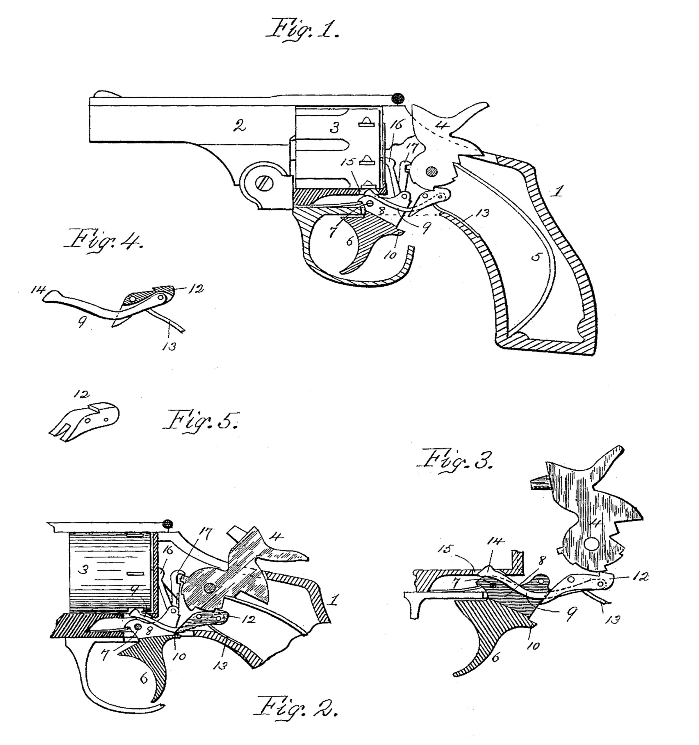
The drawings represent in Figure 1 a sectional elevation of a fire-arm embodying my improvements with the hammer at half-cock. Fig. 2 is a side view of a portion of the same with the hammer at full-cock and the locking-bolt in its active position. Fig. 8 shows the trigger, sear, locking-bolt, and the hammer enlarged, showing the relative position of parts immediately after the release of the hammer. Fig. 4 is a sectional elevation of the locking-bolt and sear. Fig. 5 is a perspective view of the sear.
In the accompanying drawings, 1 represents the frame of the stock portion of a revolving fire-arm, and 2 the barrel with its revolving cylinder 3. The hammer is shown at 4, mainspring at 5, and trigger at 6, pivoted at 7. Said trigger is deeply slotted longitudinally in its upper part at 8, within which slot is located the rigid locking-bolt 9, the trigger moving freely 3 without touching it. Furthermore, the rear portion of the trigger is provided with a projecting lip, 10. This lip; being located at the base of the slot 8, is adapted to wipe the lower free end of the sear 12 in the act of releasing the hammer to discharge the weapon.
The sear 12 is placed in its usual position, pivoted in the frame 1, and is held in contact with the hammer by the spring 13. In lieu of being of the usual construction its forward end is bifurcated and adapted to loosely straddle the cylinder-locking bolt 9, which is composed of a rigid curved arm bent upwardly at its free or forward end, 14, which extends through an aperture, 15, in the frame 1, and is to engage the slots in the cylinder 3 at stated intervals. This locking-bolt at its opposite or rear end is pivoted in the head of the sear, and is spring-actuated in the present instance by the sear spring 13. In lieu of the latter a second spring located in the sear may be employed to cooperate with the locking-bolt.
Pivoted to the upper part of the trigger is a pawl, 16, which serves to rotate the cylinder and align a cartridge with the bore of the barrel in the act of raising the hammer to fullcock; also, pivoted to the trigger at the same point is the lifter or pawl 17, which is ordinarily used in double-acting weapons, and by means of which a pull upon the trigger serves to raise the hammer.
The gist of my invention, as before briefly premised, is embodied primarily in a rigid cylinder-locking bolt spring-actuated and pivoted loosely to the head of the sear; secondly, in the employment of a bifurcated sear; thirdly, in deeply grooving the trigger and providing it with a rearwardly-extending lip, and, lastly, in the general relation and adjustment of said parts, whereby the trigger and sear may be operated, while the locking-bolt remains at rest until just prior to the position of the hammer to full-cock, when said bolt assumes an active position, holding the cylinder fixed. It will be observed that when the sear is in the half-cock notch with the locking-bolt disengaged from the cylinder the free end of the sear projects down below the locking-bolt, and so remains until the hammer is moved backward toward full-cock. When the sear has engaged said full-cock notch, the head of the sear is still depressed sufficiently to bring the locking-bolt against a slot in the cylinder, which latter is held fixed until the hammer is released, the discharge effected, and the hammer returned to half-cock.
The action of the above-described operative parts is as follows, presuming the hammer is positioned as shown in Fig. 3,or immediately after a discharge has occurred: The head of the sear then rests against the hammer just in front of the half-cock notch and is depressed. Such movement has rocked said sear and thrown the free bifurcated end up against the trigger, as also the free end 14 of the locking-bolt, which is now in engagement with a slot in the cylinder. A slight pull on the trigger now lifts the hammer, when the head of the sear engages the half-cock notch thereon and said sear rises,slightly rocking the locking-bolt upon the end of the sear-spring 13 as a fulcrum point. The free end of said bolt is lowered thereby and disengaged from the cylinder. The latter is then free to revolve. This occurs only when the hammer is at half-cock. Further continuous pull upon the trigger causes the lifter 17 to raise the hammer, the sear wiping along the periphery of the hammer. As said sear approaches the full-cock notch on the hammer the eccentricity of the latter again depresses the head of the sear, which act causes the free end 14 of the locking. bolt 9 to again engage a slot in the cylinder, and the relative positions of the parts—the locking- bolt and cylinder—are not changed even when the sear engages the full-cock notch. Further pull upon the trigger and movement of the latter causes the lip 10 to wipe against and press the free end of the sear upward, when the hammer is released. Thus the cylinder is held fixed during the release and fall of the hammer, as shown in Fig. 3. Movement of the cylinder cannot occur until the hammer is at half-cock, as before explained.
What I desire to claim is—
1. In revolving fire-arms, the combination, with the hammer, the bifurcated sear, and the trigger operating the latter, of the rigid spring actuated-cylinder locking bolt independently pivoted to the sear and loosely straddled by the latter, substantially as and for purposes specified.
2. In fire-arms, the combination, with the revolving cylinder having peripheral slots, the hammer 4, the trigger 6, longitudinally slotted at 8, with the lip 10 operating the sear, the rigid spring-actuated locking-bolt.9, independently pivoted to the head of the sear and adapted to release the cylinder when said sear is in the half-cock notch, substantially as herein described.
3. In fire-arms of the class herein mentioned, a revolving cylinder, 3, having peripheral slots, a trigger, 6, grooved to receive a locking-bolt, combined with a sear, 12, a locking-bolt, 9, independently pivoted to said sear, which latter engages the trigger, whereby the hammer, when at full-cock, serves to actuate the sear and locking-bolt to hold the cylinder fixed, as and for purposes stated.
4. The combination, with the cylinder 3, its actuating-paw1:16, the trigger 6, and its operating mechanism—the lifter 17 and sear 12—of the rigid spring-actuated locking-bolt 9, pivoted upon the head of the sear and adapted to engage the cylinder when the hammer is at full-cock or after the fall thereof, substantially as herein set forth.
In testimony whereof I affix my signature in presence of two witnesses.
ARTHUR K. HOOD.
Witnesses:
H. E. LODGE,
F. CURTIS.