
US 391613
UNITED STATES PATENT OFFICE.
ARTHUR F. HOOD, OF HOPKINTON, ASSIGNOR TO THE JOHN P. LOVELL ARMS COMPANY, OF BOSTON, MASSACHUSETTS.
REVOLVER.
SPECIFICATION forming part of Letters Patent No. 391,613, dated October 23, 1888.
Application filed April 9, 1888. Serial No. 270,055. (No model.)
To all whom it may concern:
Be it known that I, ARTHUR F. HOOD, a citizen of the United States, residing at Hopkinton, In the county of Middlesex and State of Massachusetts, have invented certain new and useful Improvements in Extractors for Revolvers; and I do hereby declare the following to be a full, clear, and exact description of the Invention, such as will enable others skilled in the art to which it appertains to make and use the same, reference being had to the accompanying drawings, and to letters or figures of reference marked thereon, which form a part of this specification.
This invention relates to fire-arms, particularly to that class of pistols having a revolving cylinder which contains a series of cartridge-shells, and from which the latter, when empty, are ejected in the act of breaking or opening the weapon.
My improvements consist in the arrangement of parts by which the “extractor-lifter,” so called, is enabled to operate the extractor for greater distance, and thus easily and readily discharge the empty shells completely from the cylinder. This movement of the extractor-lifter, to cause corresponding greater travel or
throw in the extractor, is effected by mounting the lifter upon a pivot secured in the joint of the weapon parallel with but below the pin which unites the barrel with the stock portion of the weapon. By this means a small movement of the actuating-lug which engages the stock of the weapon when in the act of breaking the latter causes a very much increased travel in the active end of the extractor-lifter which operates the extractor. The travel of the latter can be regulated by the distance at which the pivot of the extractor-lifter is placed below the pin which unites and is common to the two parts of the weapon—the barrel and stock portions.
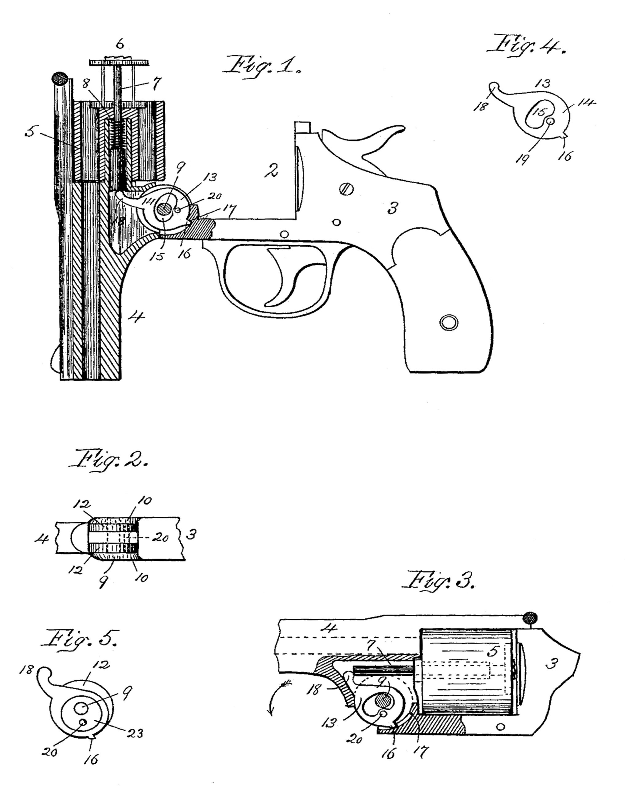
The drawings represent, in Figure 1, a longitudinal sectional elevation of a fire-arm embodying my invention and with the extractor in position just after ejecting the empty shells. Fig. 2 is a plan of the connecting-joints which unite the barrel and stock portions. Fig. 3 is a sectional elevation of a portion of the weapon, showing the relative positions of the extractor and lifter when the weapon is locked. Fig. 4 is a side elevation of the extractor-lifter. Fig. 5 is a modification in the manner of mounting the extractor-lifter.
In the accompanying drawings, 2 represents a fire-arm of the class above premised formed of the stock portion 3 and the barrel portion 4, and in which the several component parts in general bear the same relation and operate substantially as hitherto practiced. The revolving cylinder is shown at 5 as mounted upon the barrel portion 4, and is provided centrally with a spring-actuated extractor, 6, having an actuating-rod, 7. The spring 8 is so adjusted in position as to retain the extractor flush with the rear end of the cylinder, except when the weapon is “broken” in the act of removing the empty shells or of unloading, if so desired.
In fire-arms of the above-mentioned class the two main portions—stock 3 and barrel 4— are united at a point in front of the cylinder with a stout pin, 9, which interconnects these two portions. The hinge parts of each piece are composed of two semicircular ears, 10 10 12 12, parallel one with the other and arranged respectively on the stock and barrel, those on the latter fitting snugly within said ears formed upon the stock. By this construction a space exists between the ears 12 12 of the barrel portion, and within this I have disposed the extractor-lifter 13.
Hitherto in the class of fire-arms before premised the extractor-lifter has been pivoted, mounted, or operated upon the pin 9, which serves to unite the barrel and stock portions of the fire-arm; but in this arrangement the throw of the lifter is limited and the travel of the extractor has not been sufficient to entirely clear the empty shells from the cylinder, particularly when a long shell is employed, and such shells are usually removed manually. In my mechanical arrangement I pivot the extractor-lifter within the joint of the fire-arm, but at a point below the pivotal union of the barrel and stock portions. This extractor-lifter 13 is composed of a circular disk, 14, interiorly apertured at 15, in order to permit rocking movement of the lifter independently of and freely about the pin 9, which passes transversely through it. Exteriorly disposed and diametrically opposite are formed a short spur or lug, 16,which contacts with the shoulder 17 on the stock-piece 3, and a long arm, 18, the extremity of the latter being in alignment with the end of the actuating-rod 7. Below the aperture and in the extractor-lifter is bored a hole, 19, which is aligned with corresponding ones formed in the ears 12 12 o0n the barrel portion 4 and adapted to receive a pin, 20. Thus the extractor-lifter is pivoted independently of and within the hinge of the barrel portion. By mounting the lifter 13 upon a pivot, 20, independently of and below the main pivot of the weapon, the travel of the arm 18, which contacts with the extractor-rod, is proportionately increased by the distance of said pivot 20 below the hinge-pin 9. Hence an increased throw in the extractor is produced, and a long cartridge is easily and entirely ejected from the cylinder.
In the operation of this weapon containing my improvements (presuming the weapon is locked) the extractor-lifter 13 is shown in Fig. 3 pressed forward, with the extractor-pin 7 resting against the end of the arm 18, and with the extractor in an inactive position. Upon release of the catch and swinging downward of the barrel, the stock portion remaining at rest and in the position as shown in Fig. 1, the lug 16 meets and contacts with the shoulder 17 0n the stock 3. Upon further and continued turning of the barrel about the pivot 9 to open the weapon, the extractor-lifter now simultaneously turns upon its pivot 20, the lug 16 being advanced toward the muzzle of the barrel. This act compels the opposite or rear swinging movement of the arm 18, which wipes against the extremity of the extractor-pin 7 and lifts the extractor, the latter carrying with it the cartridge-shells, which are thereby withdrawn from the cylinder. Upon completion of this act and swinging of the barrel and stock portions about their common hinge to close and lock the weapon, reverse movement of the extractor-lifter is effected by the action of the spring 8, which causes the extractor to retreat to its inactive position and pushes with it the lifter, which is returned to the position shown in Fig. 3, when the latter is again in readiness to actively advance the extractor upon breaking of the weapon.
In Fig. 5 a modification is shown by a circular plate, 23, which is eccentrically mounted upon the hinge-pin 9, while the stud 20, set in the hinge of the barrel portion 4, compels said plate to rotate with the latter. Moreover, the extractor-lifter loosely fitting about said plate 23 is free to rock upon the opening or closing of the weapon. By this arrangement the center of rocking movement in the lifter is below the center of the hinge pin uniting the barrel and stock portions of the weapon, and the same resultant effect is produced, which effect is the object of my present invention.
What I desire to claim is—
1. In revolving fire-arms composed of a barrel and stock portions pivotally united, a revolving cylinder and an extractor actively operated by the breaking of the weapon, the extractor-lifter pivotally connected to the barrel portion within the joint of the weapon, but independently of and below a plane parallel with the bore drawn through said pin, which joins the barrel and stock portions, substantially as stated.
2. In fire-arms, the combination, with the stock portion, the barrel portion pivotally united therewith having a revolving cylinder and a spring-actuated extractor which reciprocates in the latter, of the extractor-lifter pivoted upon the hinge part of the barrel beneath the pivot common to the barrel and stock, said extractor-lifter operating to advance the extractor in the act of breaking the weapon, substantially as and for purposes set forth.
3. In combination with the stock portion 3; barrel portion 4, and the pivotal connection 9, which unites them, the apertured extractor-lifter 13, pivoted to the barrel portion otherwise than by pivot 9, and provided with the spur 16 and arm 18, which operate when the weapon is opened to actively advance the extractor and discharge the cartridge-shells, as herein described.
4. In fire-arms, the stock 3, having a pair of ears, 10, formed thereon, a transverse pin, 9, attached to said ears, a barrel having a pair of perforated ears, 12, through which said pin passes, and an extractor-lifter, 13, which is eccentrically pivoted to said barrel, provided with a central aperture to leave room for said.
pin and allow the motion of said extractor- lifter on its pivot, and a projection extending under the cartridge-extractor, for the purpose of lifting the Same, substantially as set forth.
5. The barrel portion 4, cylinder 5, spring- actuated extractor 6,and pin 7, combined with the apertured extractor-lifter 13, independently pivoted to the barrel portion below the hinge of the weapon and provided with the arm 18 to engage the extractor-pin 7, and the spur 16 to contact the shoulder 17 in the stock 8 upon movement or swinging of the barrel and stock about their common pivot 9, substantially as herein stated.
6. The combination, with the stock portion 3, the barrel portion 4, and the pin 9, common to them both, of the pin 20, located in said barrel portion beneath the axial point of rotation of the latter, and the extractor-lifter 13, secured thereon, provided with the spur 16 and arm 18 and apertured at L5, to permit rocking of said lifter transversely and independently of the common pivot 9, substantially as herein described.
In testimony whereof I affix my signature in presence of two witnesses.
ARTHUR F. HOOD.
Witnesses:
H. E. LODGE,
F. CURTIS.