
US 392503
UNITED STATES PATENT OFFICE.
CARL J. EHBETS, OF HARTFORD, CONNECTICUT, ASSIGNOR TO THE COLT’S PATENT FIRE ARMS MANUFACTURING COMPANY, OF SAME PLACE.
REVOLVER.
SPECIFICATION forming part of Letters Patent No. 392,503, dated November 6, 1888.
Application filed August 27, 1888, Serial No. 283,852. (No model.)
To all whom it may concern:
Be it known that I, CARL J. EHBETS, of Hartford, in the county of Hartford and State of Connecticut, have invented a new Improvement in Revolvers; and I do hereby declare the following, when taken in connection with accompanying drawings and the letters of reference marked thereon, to be a fall, clear, and exact description of the same, and which said drawings constitute part of this specification, and represent, in—
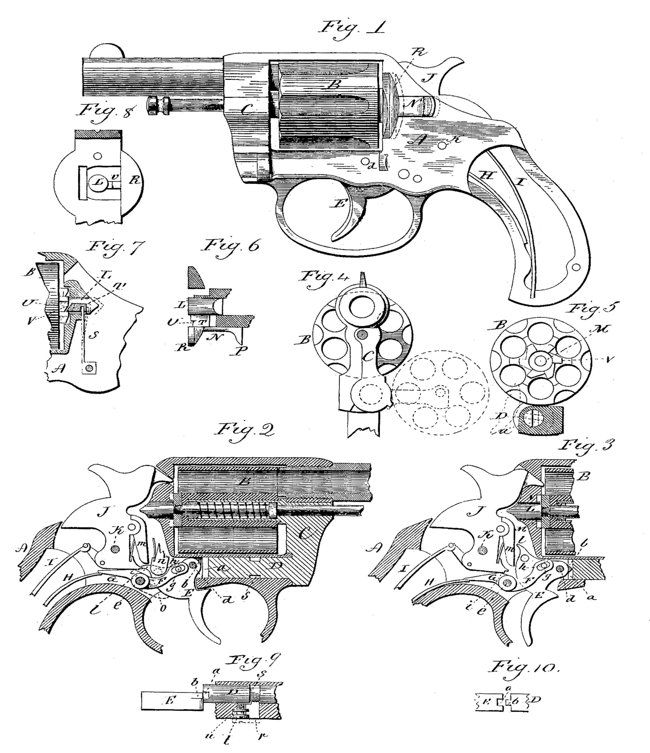
Figure 1, a side view of the revolver complete; Fig. 2, @ longitudinal sectional side view showing the parts in the normal position; Fig. 8, the same as Fig. 2, showing the parts as after the discharge of the hammer and before the release of the trigger; Fig. 4, a forward end view: Fig. 5, a transverse section through the frame, showing a rear end of the cylinder and the spindle with the crane; Fig. 6, a horizontal section showing a top view of the locking-bolt of the cylinder, its slide, and locking- dog; Fig..7, a sectional side view showing the locking dog and bolt for the cylinder; Fig. 8, a transverse section in rear of the cylinder, showing front view of the cylinder-locking bolt and dog; Fig. 9, a horizontal section of the frame,showing top view of the trigger and crane-spindle; Fig. 10, a modification in the engagement between the trigger and crane-spindle.
This invention relates to an improvement in that class of revolvers in which the cylinder is hung in a part of the frame, which part of the frame is arranged upon an axis below the cylinder and parallel with the axis of the cylinder, so that the cylinder may be turned laterally outward upon the said pivot of the frame for loading or for ejection of shells. Parts of the invention, however, are applicable to other classes of fire arms; and the invention consists in the construction as hereinafter described, and particularly recited in the claims.
A represents the frame, having a recess formed therein to receive the cylinder B, the frame at the rear carrying the lock mechanism and the barrel attached to the forward end in the usual manner. The forward part of the frame is divided, a portion, C, forming what I call the “crane.”. This portion C is constructed with a spindle, D, arranged in a corresponding seat below the cylinder, parallel with the axis of the cylinder, and so as to form a pivot upon which the said crane may swing laterally outward and inward. This crane carries the cylinder B on a spindle formed as a part of the crane in the usual manner, so that the cylinder may swing with the crane from its opening in the frame, as indicated in broken lines, Fig. 4, for charging the cylinder or for ejecting the shells therefrom, the ejector being of common construction.
It is desirable that possible contact of the hammer with the cartridge in the cylinder shall be prevented except when the cylinder is in its proper position, and to prevent the outward movement of the cylinder except when the hammer shall have been so far retracted as to take its nose out of the path of the cylinder. To accomplish this object, the rear end of the spindle D is constructed with a vertical groove or notch, a; which, when the cylinder is in the closed position, stands vertically and in the plane of a finger, b, on the hub of the trigger E, (see Fig. 9, ) which is hung in the frame upon a pivot, d, in the usual manner.
When the parts are in the normal position, as seen in Fig. 2, the trigger is forward and the finger b stands in the plane of the groove a of the crane-spindle, but so far to the rear of it as to be out of engagement therewith; therefore with the parts in this position the cylinder-crane is free to be turned upon the axis of the crane. If, however, with the parts in this position the trigger be pulled, as indicated in. Fig. 3, the finger & passes into the groove a of the crane-spindle and interlocks therewith, so as to prevent the crane from turning. Consequently the cylinder cannot be turned from its place in the frame except when the trigger is in the normal position.
If the cylinder be thrown outward, as indicated in broken lines, Fig. 4, the result will be to turn the notch a to a plane out of the plane of the finger b on the trigger, as indicated in broken lines, Fig. 5. Consequently while the cylinder is in this outwardly-turned position the rear end of the spindle serves as a stop for the trigger and the trigger cannot be pulled. Any movement of the hammer is therefore avoided.
If the cylinder be not properly returned to its place, the groove a of the crane spindle will not coincide with the path of the finger b. Consequently the trigger cannot be pulled to discharge the hammer until the cylinder is in its proper position for firing.
To produce a rebound of the hammer and employ the same spring as the trigger-spring, a two-armed lever, F G, is hung upon a pivot, e, in the frame below the hammer, in rear of the trigger, and the one arm, F, extending forward, is engaged with a stud, g, upon the trigger by means of a slot, h, in the lever, so that both the trigger and lever must move together, their axes being parallel. The arm G of the lever extends rearward and rests upon a rebound-spring, H, arranged in the frame beneath the mainspring I. The hammer J is hung upon its pivot K in the frame in the usual manner above the said arm G. The upper surface of this arm G forms a cam, i, adapted to bear upon the arm below and forward of the hammer-pivot. The tendency of the rebound-spring H is to force the arm G of the lever upward, and this upward movement of the arm G produces a corresponding downward movement of the other arm, and that downward movement of the said other arm is communicated to the trigger, tending to force the trigger to its forward or normal position, as seen in Fig. 2. The spring, however, yields under a pull of the trigger, such pull of the trigger turning the lever F G, say, as to the position seen in Fig. 3, and which is the position the parts occupy immediately after the discharge of the hammer and before the trigger is free. The said discharge of the hammer permits it to fly forward under the action of its spring and impart its blow to the cartridge in the cylinder. Now, when the trigger is free the rebound-spring H turns the arm upward and the trigger forward. The upward movement of the arm G operates as a cam upon the hammer and turns the hammer upon its pivot backward, as seen in Fig. 2, to such an extent as to take the nose of the hammer out of the path of the cylinder or the head of the cartridge therein, this rebound of the hammer being desirable in order to clear the nose of the hammer from the cylinder or cartridge. When the trigger is pulled, its nose l engages a latch, m, hinged to the hammer above the pivot, and so that a continued pull of the trigger will throw the hammer to the full-cocked position, where the nose will escape from the latch m and allow the hammer to fly forward, as seen in Fig. 3, the pull of the trigger first imparting the rotation to the cylinder by means of the hand n, hang upon the trigger in the usual manner, (Not fully illustrated because well known.) Under this arrangement the rebound-spring serves also as the trigger-spring, and as the pull of the trigger is prevented except when the cylinder is in the proper position, it follows that the hammer cannot be discharged except when the cylinder is in such proper position.
The bearing between the cam-shaped portion of the rebound-lever G F is in such relation to the hammer, when the hammer stands in the rebound position, as seen in Fig. 2—that is, in a direct line between the axis of the pivot of the hammer and lever—and the point of the latch m extends down so as to nearly touch the top of the nose l of the trigger, that if the hammer therefore should be forced forward from its rebound position, as by a blow from a fall or otherwise, the latch m will strike the nose l of the trigger, the tendency of which will be to turn the trigger forward; but, as the arm G of the rebound-lever is by such accidental movement of the hammer depressed, the other arm F of the said lever at the same time, through the stud g upon the trigger, tends to turn the trigger backward against the latch m, and thus the hammer is positively locked, so that it is impossible to bring its nose into contact with the primer of a cartridge.
To give a greater support to the rebound-lever when the parts are in the normal position, an extension, o, may be made from the hub of the rebound-lever down below, and so as to bear upon the corresponding surface of the trigger, as indicated in broken lines, Fig. 2, so as to take any undue strain which would otherwise come upon the stud g. In this case the latch m presses down on the trigger, while the trigger presses on the extension o, thus preventing the hammer from moving forward; but ordinarily this additional support will be unnecessary.
In the frame in rear of the cylinder is a central longitudinal bolt, L. (See Figs. 6, 7, and 8.) This bolt is in line with the axis of the cylinder, and when the cylinder is in the closed position the bolt centers a corresponding concentric recess, M, in that end of the ratchet or cylinder, and, as seen in Figs. 2 and 3, when so engaged the cylinder is held in its proper position for firing, and from which it cannot be removed until the bolt L is withdrawn. This bolt L is attached to or made a part of a slide, N, on the outside of the frame, (see Figs. 1 and 6), the said slide being provided with thumb-piece, P, by which it may be drawn backward, as indicated in broken lines, Fig. 1. The forward portion, R, of this slide forms part of the shield in rear of the cylinder. Within the frame a spring, S, is provided, the tendency of which is to force the bolt into its forward or engaging position, as seen in Fig 7. The connection T between the bolt and the slide forms a bevel-faced dog, U, at one side of the bolt L, and this dog U stands in the path of the teeth V of the ratchet on the end of the cylinder, and so as to interlock therewith, the nose of the dog being opposed to the backward rotation of the cylinder. The bevel of the nose permits the ratchet to escape when turned in the advance direction. This dog therefore serves as a positive stop to prevent a backward rotation of the cylinder and coacts with the advancing hand of the trigger to rigidly hold the cylinder at the instant of firing—that is to say, upon the pull of the trigger the hand turns the cylinder in the usual manner until it reaches its position for firing, and there holds until the hammer has been discharged. In such rotation of the cylinder the dog U has escaped from one tooth and engaged the next, so that while the trigger is held in the pulled position the cylinder is positively engaged, as before described.
I have represented the rear end of the crane-spindle as constructed with a groove and the trigger constructed with a corresponding finger on the forward side of its hub; but it will be understood that this order may be reversed and the spindle constructed with the projection and the trigger with the groove, as seen in Fig. 10; or any suitable interlocking recesses and projections in the adjacent faces of the spindle and trigger may be employed. I therefore do not wish to be understood as limiting the invention to the formation of the groove and tongue on the particular parts as first described, it only being essential to the invention that the trigger can only interlock with the spindle when the cylinder is in proper position for firing. The crane is held in place by means of a bolt, r, through the side of the frame, (see Fig. 9,) the nose of the bolt entering a corresponding annular groove, s, in the spindle. This bolt is operated by means of a screw, t, introduced into the frame at the side of the bolt r, the head of the screw constructed with an annular groove, u, which engages the bolt t, and so that by turning the screw in either direction the bolt will be moved accordingly because of the engagement of the bolt with the groove of the screw and as indicated in broken lines, Fig. 9.
I claim—
1. In a revolver, a crane carrying the cylinder, the said crane hung by a spindle in a longitudinal bearing beneath and parallel with the axis of the cylinder, and so that the cylinder may be turned laterally from or into its place in the frame, combined with the trigger hung in rear of the spindle of the crane, the rear end of the spindle and the corresponding surface of the trigger constructed, the one with a projection and the other with a corresponding recess, and whereby said trigger and spindle are adapted to engage each other under a pull of the trigger only when the cylinder is in the proper position for firing, substantially as described.
2. In a revolver, a crane carrying the cylinder, the said crane hung in the frame by a spindle in a longitudinal bearing beneath and parallel with the axis of the cylinder, and so that the cylinder may be turned laterally from or into its place in the frame, combined with the trigger hung in rear of the spindle of the crane, the spindle of the crane constructed with a groove in its rear end, and the trigger constructed with a finger forward of its hub corresponding to said groove and in the plane of said groove when the cylinder is in position for firing, substantially as and for the purpose described.
3. The combination of a trigger hung upon the frame, a hammer hung upon a pivot in the frame in rear of the trigger, a lever hung upon a pivot between the trigger and hammer, one arm of said lever extending forward and into engagement with the trigger, the other arm of the said lever extending rearward beneath the hammer, and so as to form a cam beneath the hammer forward of its pivot, with a spring the tendency of which is to turn the rear arm of the said lever toward the hammer, substantially as and for the purpose described.
4. The combination, in a revolver, of a crane hung upon a spindle beneath the cylinder and parallel with the axis of the cylinder, the cylinder hung to said crane and so as to swing laterally toward and from its place in the frame, the trigger hung in the frame in rear of said spindle, the rear end of the said spindle and the forward surface of the hub of the trigger constructed with corresponding interlocking devices which are adapted to interlock when the cylinder is in its proper position for firing, the hammer hung in the frame in rear of the pivot, a lever, F G, hung in the frame between the said trigger and hammer, one arm of the said lever extending forward into engagement with the trigger, the other arm extending rearward beneath the hammer and constructed with a cam-shaped surface adapted; to bear upon the hammer forward of its pivot, and a spring, H, adapted to turn the said arm G toward the hammer, substantially as described.
5. In a revolver in which the cylinder is arranged to swing laterally outward and inward from and to its place in the frame, a central bolt, L, in the frame longitudinally movable and adapted to engage the cylinder when in its place in the frame, the slide N outside the frame and connected with said bolt, the connection between said slide and bolt constructed with a dog, U, adapted to engage the cylinder, so as to prevent its backward rotation, but yet permit the cylinder to escape in the forward rotation, substantially as and for the purpose described.
CARL J. EHBETS.
Witnesses:
F. F. KNOUS,
A. L. ULRICH.