
British 329
Lever cocking revolver
LETTERS PATENT to Auguste Edouard Loradoux Bedford, of 16, Castle Street, Holborn, in tlie City of London, Patent Agent, for the Invention of “ Improvements xir the Construction of Revolving ok Repeating Fire-arms.”—A communication.
Sealed the 6th April 1853, and dated the 11th October 1852.
PROVISIONAL SPECIFICATION left by the said Auguste Edouard Loradoux Bellford at the Office of the Commissioners of Patents, with his Petition, on the 11th October 1852.
I, Auguste Edouard Loradoux Bellford, of 16, Castle Street, Holborn, in the City of London, Patent Agent, do hereby declare the nature of the said Invention for “ Improvements in the Construction of Revolving or Repeating Fire-arms,” to be as follows:—
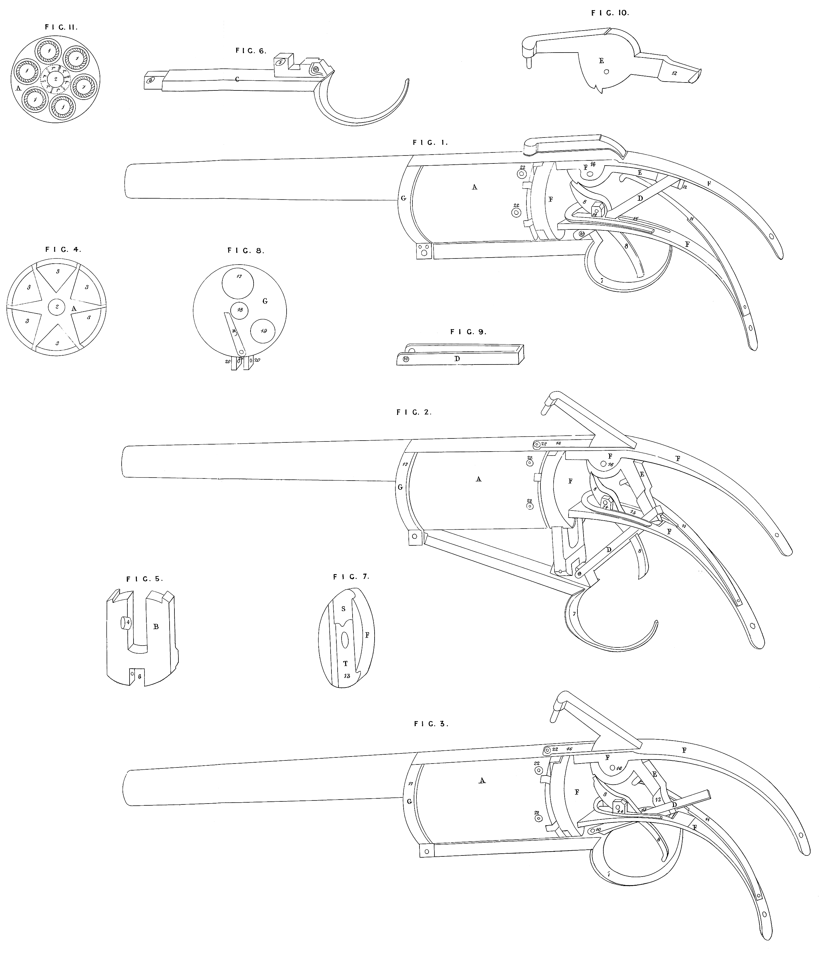
Fig. 1, represents the gun in its usual position, after having been discharged. Fig. 2, represents it with the guard lever and sliding crotch drawn down for the purpose of revolving or cocking the piece. Fig. 3, represents it with the guard lever pushed up, leaving it cocked and in position to be discharged. Fig. 4, represents the back face of the rotating breech, with the inclined planes made in triangular form. Fig. 5, represents the sliding crotch, with the stud projecting from the front face of the said crotch. Fig. 6, represents the guard lever, with the stud and curved hole by which it is attached to the sliding crotch; also the oblong axis hole at the forward end of it, by which it is attached to the sliding plate, the said holes being made curved and oblong for the purpose of allowing the said lever to recede when it is drawn down, thus causing the sliding crotch to be drawn vertically from its usual position.. Fig. 7, represents the forward end or face of the lock frame with the recess (showing the irregular form) for the sliding crotch to work in, allowing it to move vertically and horizontally. Fig. 8, represents the back face of the barrel plate with the spring in it, which serves to press the breech and crotch back from the barrel. It also serves to prevent the rotating breech from turning backwards when the sliding crotch is forced upwards by the end of it operating against the circular rachet made on the front face of the rotating breech. It also represents the studs and mortise to which the axis of the guard lever is fixed, also the hole where the charges are loaded into the rotating breech, and the hole where the barrel is attached to .said plate. Fig. 9, represents the link connecting the guard lever with the hammer. Fig. 10, represents the hammer. Fig. 11, represents the front face of the rotating breech, with the six chambers to receive the charges. At the end of each chamber, where they connect with the barrel, is a recess countersunk in such a manner as to form a double connection with each chamber and the barrel, viz., a portion of the rotating breech is made (within the recess) to project and fit tight into the chamber of the barrel, and the outside circle of the recess is made to fit the outside circle of the barrel, thus forming a double connection between the breech and the barrel; by means of the recesses and connection with the barrel made in th is way a partition is formed between each chamber of the rotating breech, which serves to prevent lateral fire (when the piece is exploded) in case the connection between the breech and barrel should not be perfectly tight, thus rendering it safe and secure, and not liable to explode more than one charge at a time. It also represents the axis hole and the circular ratch around said axis hole. A, represents the rotating chambered breech, made of steel or other metal, in the front face of which are made six chambers (marked 1,) to receive the charges. Through the centre of the revolving barrel is made a hole 2, for it’s axis. Around the axis hole is a circuliar ratchet r, on which a spring operates for the purpose of holding it to it’s place, and to prevent it’s turning backwards when the sliding crotch is forced up to it’s place. In the back face of the rotating breech are six inclined planes made in a triangular form (and marked 3), made for the purpose of rotating the breech by the operation of the sliding stud 4, (projecting from the front face of the sliding crotch B, acting upon the inclined planes, so that by drawing down the sliding crotch B, by its connection with the curved oblong hole 5, in the guard lever C, the said breech shall be rotated sufficient to bring a located chamber in line with the chamber in the barrel. B, represents the sliding crotch 3, and it’s sliding stud 4, which is made of iron or steel, and is intended to hold the rotating breech to it’s place, sustain the recoil when fixed, and rotate the breech when drawn down. The crotch is moved to and from it’s place by the guard lever C. At the lower end of the crotch is a mortise 6, by which it is connected with the guard lever C, by means of a pin or screw passing through a hole in the mortise, and the curved oblong hole 5, in said guard lever C, represents the guard lever, the back part whereof 7, forms the bow of the guard which covers the trigger 8. At the forward end is an oblong hole 9, which serves for its axis, and to connect it with the barrel plate. Back from said axis, and near where the curve or bow which covers the trigger commences, is a stud and curved oblong hole 5, made to fit the mortise 6, in the sliding crotch, so that the guard is made to operate as a lever to draw the crotch from and to move it to it’s place. Back from the curved oblong hole 5, is an axis hole 10, to which a link D, is attached, connecting it with the hammer E, thus causing the mainspring 11, to hold the guard lever and crotch firmly up to their places, and also to admit of the piece being cocked by drawing down the guard lever. D, represents a link made of iron or steel, at the lower end of which is made a hole 10, which serves as an axis, and to connect it with the guard lever. The said link is designed to connect the guard lever and hammer together. E, represents the hammer, the back end 12, of which is formed in such a manner as to keep the link from becoming detached, but still allowing it to slide up and down freely when the hammer is cocked. F, represents the lock frame made of iron or other metal. In the forward end or face of it is made a recess 13, of irregular form, for the sliding crotch to work in, the upper part, marked S, projecting forward for the purpose of inclining the crotch and rotating breech forward, and connecting it with the barrel, when the crotch is pressed up; the lower part, marked T, is sunk deeper into the face of the lock frame than the upper, for the purpose of allowing the sliding crotch and rotating breech to recede when the said breech is retracted from the barrel. A little distance back from the front part of the lock frame, and on the lower side of it, is a stud and mortise 14, to which the trigger 8, is attached; also, a long mortise 15, through which the link D, passes. On the upper side of the lock frame, and over the trigger, is a stud and mortise 16, through which the hammer passes, and to which it is attached. G, represents the barrel plate, to upper part 17, of which the barrel is attached, with it’s back end projecting through it to meet the chambers of the rotating breech. At the centre of the plate is a hole 18, through which the bolt which forms the axis of the rotating breech passes. A little below and on one side of the centre is a hole 19, where the cartridges or powder and balls are entered to the chambers of rotating breech. At the lower part of it the studs and mortise 20, are made, to which the axis of the guard lever is attached. On the back face of it, and the part which conies next to the chambers of the rotating breech, is fixed a spring 21, the : end of which presses against the front face of the rotating breech, and which serves to press the breech and crotch back from the barrel, thus leaving the breech free to be rotated. It also serves to prevent the rotating breech from turning backwards (when the sliding crotch is forced up) by the end of it operating against the circular ratchet made on the front : face of the rotating breech. On the periphery, and near the back end of the rotating breech, are six recesses (marked 22), in which are made the touch-holes leading to the chambers of the rotating breech. The said recesses are made to receive each a disc, one side of which is covered with percussion powder. The said discs are to be pressed into the recesses with the side on which the percussion powder is placed, to come in contact with the holes for the purpose of priming. By using discs for priming instead of percussion caps the rotating breech is not liable to be clogged by particles of copper blowing off from the priming, so that the breech will not rotate as is the case when caps are used, and the recesses in which the discs are placed will prevent lateral fire, so that when a disc is exploded the fire from it cannot communicate with those which are contiguous.
To load a fire-arm thus constructed draw down the guard lever so as to bring the hammer to the half cock, which will cause the lotating breech to be retracted from the barrel, and left free to be rotated (towards the right) by the hand, so that each chamber may be loaded by turning them to the hole 19, in the barrel plate. This being done, and the chambers loaded, place the discs in the recesses, and press them in tight.
What is claimed and desired to be secured by Letters Patent is, the construction of the sliding sliding crotch substantially as described, to enable it to perform the double purpose of revolving the breech and wedging it up against the barrel, and the combination of the sliding-crotch and guard lever constructed and arranged as specified, by which the breech is rotated, wedged forward, and the gun cocked by one motion back and forth of the trigger guard or it’s equivalent, substantially as above described.
SPECIFICATION in pursuance of the conditions of the Letters Patent, filed by the said Auguste Edouard Loradoux Bellford in the Great Seal Patent Office, on the 11th April 1853.
TO ALL TO WHOM THESE PRESENTS SHALL COME, I,
Auguste Edouard Loradoux Bellford, of 16, Castle Street, Holborn, in the City of London, Patent Agent, send greeting.
WHEREAS Her most Excellent Majesty Queen Victoria, by Her Letters Patent, bearing date the Eleventh day of October, in the year of our Lord One thousand eight hundred and fifty-two, in the sixteenth year of Her reign, did, for Herself, Her heirs and successors, give and grant unto me, the said Auguste Edouard Loradoux Bellford, Her special license that I, the said Auguste Edouard Loradoux Bellford, my executors, administrators, and assigns, or such others as I, the said Auguste Edouard Loradoux Bellford, my executors, administrators, and assigns, should at any time agree with, and no others, from time to time and at all times thereafter during the term therein expressed, should and lawfully might make, use, exercise, and vend, within the United Kingdom of Great Britain and Ireland, the Channel Islands, and Isle of Man, an Invention, communicated to me by a foreigner residing abroad, for. “ Improvements in the Consteuction of Revolving ob Repeating Fiee-aems,” upon the condition (amongst others) that I, the said ^uguste Edouard Loradoux Bellford, by an instrument in writing under my hand and seal, should particularly describe and ascertain the nature of the said Invention, and in what manner the same was to be performed, and cause the same to be filed in the Great Seal Patent Office within six calendar months next and immediately after the date of the said Letters Patent.
NOW KNOW YE, that I, the said Auguste Edouard Loradoux Bellford, do hereby declare the nature of my said Invention, and in what manner the same is to be performed, to be particularly described, and ascertained in and by the following statement (that is to say): ‘
This Invention relates to new and useful improvements in the construction of what are usually known as revolving or repeating fire-arms.
Figure 1, represents the gun in its usual position, after having been discharged. Figure 2, represents it with the guard lever and sliding crotch drawn down for the purpose of revolving or cocking the piece. Figure 3, represents it with the guard lever pushed up, leaving it cocked and in position to be discharged. Figure 4, represents the back face of the rotating breech with the inclined planes made in triangular form. Figure 5, represents the sliding crotch with the stud projecting. from the front face of the said crotch. Figure 6, represents the guard lever with the stud and curved hole by which it is attached to the Sliding crotch ; also the oblong axis hole at the forward end of it, fey which it is attached to the sliding plate,, the said holes being made curved and oblong for the purpose of allowing the said lever to recede when it is drawn down, thus causing the sliding crotch to be drawn vertically from its usual position. Figure 7, represents the forward end or face of the lock frame with the recess (showing the irregular form) for the sliding crotch to work in, allowing it to move vertically and horizontally. Figure 8, represents the back face of the barrel plate with, the spring in it, which serves to press the breech and crotch, back from the barrel. It also serves to prevent the rotating breech from turning backwards when the sliding crotch is forced upwards by the end of it operating against the circular ratchet made on the front face of the rotating breech. It also represents the studs and mortise to which the axis of’ the guard lever is fixed, also the hole where the charges are loaded into the rotating breech, and the hole where the barrel is attached to said plate. Figure 9, represents the link connecting the guard lever with the hammer. Figure 10, represents the hammer. Figure 11, represents the front face of the rotating breech, with the six chambers to receive the charges. At the end of each chamber where they connect with the barrel is a recess countersunk in such a manner as to form a double connection with each chamber and the barrel, videlicet, a por-; tiou of the rotating breech is made (within the recess) to project and fit’ tight into the chamber of the barrel, and the outside circle of the recess’ is made to fit the outside circle of the barrel, thus forming a double connection between the breech and the barrel; by means of the recesses and connection with the barrel made in this way a partition is formed; between each chamber of the rotating breech, which serves to prevent lateral fire (when the piece is exploded) in case the connection between the.breech and barrel should not be perfectly tight, thus rendering it safe and secure, and not liable to explode more than one charge at a titne; it also represents the axis hole and the circular ratch around, said axis hole. A, represents the rotating breech made of steel or other metal, in the front face of which are made six chambers (marked 1,) to receive the charges. Through the centre of the revolving breech is made a hole 2, for its axis. Around the axis hole is a circular ratchet.
on which a.spring operates for the purpose of holding it to its placev and to prevent its turning backwards when the sliding crotch is forced up to its place. On the back face of the rotating breech are six inclined planes made in a triangular form (and marked 3), made for the purpose of rotating the breech by the operation of the sliding stud 4, (projecting from the front face of the sliding crotch B, acting upon the inclined planes, so that by drawing down the sliding crotch B, by its connection with the curved oblong hole 5, in the guard lever C> the said breech shall be rotated sufficient to bring a located chamber in line with the chamber in the band. B, represents the sliding crotch 3, and its sliding stud 4, which is made of iron or steel, and is intended to hold the rotating breech to its place, sustain the recoil when fixed, and rotate the breech when drawn down. The crotch is moved to and from its place by the guard lever C. At the lower end of the crotch is a mortise 6, by which it is connected with the guard lever C, by means of a pin or screw passing through a hole in the mortise, and the curved oblong hole 5, in said guard lever. C, represents the guard lever, the back part whereof (7,) forms the bow of the guard which covers the trigger 8. At the forward end is an oblong hole 9, which serves for its axis, and to connect it with the barrel plate. Back from said axis, and near where the curve or bow which covers the trigger commences, is a stud and curved oblong hole 5, made to fit the mortise 6, in the sliding crotch, so that the guard is made to operate as a lever to draw the crotch from and to move it to its place. Back from the curved oblong liole 5, is an’ axis hole 10, to which a link D, is attached, connecting it with the hammer E, thus causing the mainspring 11, to hold the guard lever and crotch firmly up to their places, and also to admit of the piece being cocked by drawing down the guard lever. D, represents a link made of iron or steel, at the lower end of which is made a hole 10, which serves as an axis, and to connect it with the guard lever. The said link is designed to connect the guard lever and hammer together. E, represents the hammer, the back end 12, of which is formed in such a manner as to keep the link from becoming detached, but still allowing it to slide up and down freely when the hammer is cocked. F, represents the lock frame made of iron or other metal. In the forward end or face of it is made a recess 13, of irregular form, for the sliding crotch to work in, the upper part, marked S, projecting forward for the purpose of inclining the crotch and rotating breech forward, and connecting it with the barrel, when the crotch is pressed up; the lower part, marked T, is sunk deeper into the face of the lock frame than the upper, for the purpose of allowing the sliding crotch and rotating breech to recede when the said breech is retracted from the barrel. A little distance back from the front part of the lock frame, and on the lower side of it, is a stud and mortise (14), to which the trigger 8, is attached ; also, a long mortise (15), through which the link D, passes. On the upper side of the lock frame, and over the trigger, is a stand and mortise (16), through which the hammer passes, and to which it is attached. G, represents the barrel plate, to the upper part (17), of which the barrel is attached, with its back end projecting through it to meet the chambers of the rotating breech. At the centre of the plate is a hole (18), through which the bolt which forms the axis of the rotating breech passes. A little below and one side of the centre is a hole (19), where the cartridges or powder and balls are entered to the chambers of the rotating breech. At the lower part of it the studs and mortise (20,) are made, to which the axis of the guard lever is attached. On the back face of it, and the part which comes next to the chambers of the rotating breech, is fixed a spring (21), the end of which presses against the front face of the rotating breech, and which serves to press the breech and crotch back from the barrel, thus leaving the breech free to be rotated. It also serves to prevent the rotating breech from turning backwards (when the sliding crotch is forced up), by the end of it operating against the circular ratchet made on the front face of the rotating breech. On the periphery, and near the back end of the rotating breech, are six recesses (marked 2, 2), in which are made the touch-holes leading to the chambers of the rotating breech. The said recesses are made to receive each a disk, one side of which is covered with percussion powder. The said disks are to be pressed into the recesses with the side on which the percussion powder is placed, to come in contact with the touch-holes for the purpose of priming. By using disks for priming instead of percussion caps the rotating breech is not liable to be clogged by particles of copper blowing off from the priming, so that the breech will not rotate as is the case when caps are used, and the recesses, in which the disks are placed, will prevent lateral fire, so that when a disk is exploded the fire from it cannot communicate with those which are contiguous.
To load a fire-arm thus constructed draw down the guard lever so as to bring the hammer to the half cock, which will cause the* rotating breech to be retracted from the barrel, and left free to be rotated (towards the right) by the hand, so that each chamber may be loaded by turning them to the hole 19, in the barrel plate. This being done, and the chambers loaded, place the disks in the recesses, and press them in tight.
What is claimed by this Invention, and desired to be secured by Letters Patent, is, the construction of the sliding crotch substantially as described, to enable it to perform the double purpose of revolving the breech and wedging it up against the barrel, and the combination of the sliding crotch and guard lever constructed and arranged as specified, by which the breech is rotated, wedged forward, and the gun cocked by one motion back and forth of the trigger guard, or its equivalent, substantially as above described.
In witness whereof, I, the said Auguste Edouard Loradoux Bellford have hereunto set my hand and seal, this Eleventh day of April, in the year of our Lord One thousand eight hundred and fifty-three.
A. E. LORADOUX BELLFORD. (l.s.)