
British 535
“zig-zag” revolver
LETTERS PATENT to Samuel Colt, of Spring Gardens, in the County of Middlesex, Gentleman, for tlie Invention of “ Improvements in Rotating Breech Fire-arms.”—Partly a communication.
Sealed the 27th April 1853, and dated the 3d March 1853.
PROVISIONAL SPECIFICATION left by the said Samuel Colt at the Office of the Commissioners of Patents, with his Petition, on the 3d March 1853.
I, Samuel Colt, do hereby declare the nature of the said Invention for “ Improvements in Rotating Breech Fire-arms” to be as follows This Invention relates to certain novel means of rotating the breech cylinder of repeating fire-arms, which means will greatly simplify and otherwise improve the construction of the arms. Instead of the ordinary catch, taking into ratchet teeth cut on the hind end of the breech, I propose to groove the periphery of the cylinder in such a manner that a pin, by traversing the grooves, will not only effect the rotation of the cylinder, but also lock it when required. For this purpose I cut a number of parallel grooves, one for every chamber, in the periphery of the breech cylinder, and I connect these straight grooves together by means of diverging curved grooves running from near the forward end of one groove to near the hinder end of the next adjoining groove. Between these straight grooves, and running forward out of the curved grooves, are short straight grooves into which the traversing pin enters when the loaded cylinder is required to be safely locked. This pin is carried by a sliding block, working in guides, and connected by a strap or link to the hammer, the movement of which causes the traverse of the pin. When the pin is drawn back after firing it meets with an obstruction in the straight groove, which is placed there to turn it into the. diverging groove; and in passing along this latter groove it will draw round the cylinder on its axis. If the hammer is allowed to fall forward when the pin has arrived opposite the short straight groove, the pin will run up that groove and lock the cylinder, to prevent a premature discharge of the arm; but, when drawn back until it reaches the next long straight groove, it will have turned the cylinder sufficiently to bring the chamber next succeeding that last fired into a line with the barrel, and will hold the cylinder in position for firing. A ring of lateral cuts forming inclined planes is made in the grooves to allow the cylinder to rotate freely when the pin is in a line therewith, for the purpose of facilitating the loading of the chambers, which position the pin will take when the hammer is set at half-cock. Another mode in which I effect the rotation of the breech is to groove the rear end of the breech in a manner analogous to that just described, and to fit the traverse or driving pin to the lower part of the hammer. In this arrangement I shape the rear end of the breech, so that the pin may, as it is rocked by the hammer, be always in contact with the breech.
SPECIFICATION in pursuance of the conditions of the Letters Patent, filed by the said Samuel Colt, in the Great Seal Patent Office, on the 3d September 1853.
TO ALL TO WHOM THESE PRESENTS SHALL COME, I, Samuil Colt, of Spring Gardens, in the County of Middlesex, Gentlemen, send greeting.
WHEREAS Her most Excellent Majesty Queen Victoria, by Her Letters Patent, bearing date the Third day of March, in the year of our Lord One thousand eight hundred and fifty-three, in the sixteenth year of Her reign, did, for Herself, Her heirs and successors, give and grant unto me, the said Samuel Colt, Her special licence that I, the said Samuel Colt, my executors, administrators, and assigns, or such others as I, the said Samuel Colt, my executors, administrators, and assigns, should at any time agree with, and no others, from time to time and at all times thereafter during the term therein expressed, should and lawfully might make, use, exercise, and vend, within the United Kingdom of Great Britain and Ireland, the Channel Islands, and Isle of Man, an Invention for “ Improvements in Rotating Breech Fire-arms,” being partly a communication from abroad, upon the condition (amongst others) that I, the said Samuel Colt, by an instrument in writing under my hand and seal, should particularly describe and ascertain the nature of the said Invention, and in what manner the same was to be performed, and cause the same to be filed in the Great Seal Patent Office within six calendar months next and immediately after the date of the said Letters Patent.
NOW KNOW YE, that I, the said Samuel Colt, do hereby declare the nature of my said Invention, and in what maimer the same is to be performed, to be particularly described and ascertained in and by the following statement, reference being had to the Drawing hereunto annexed, and to the letters and figures marked thereon (that is to say):
This Invention relates to certain novel means of rotating the breech cylinder of repeating fire-arms whereby their construction will be greatly simplified and improved.
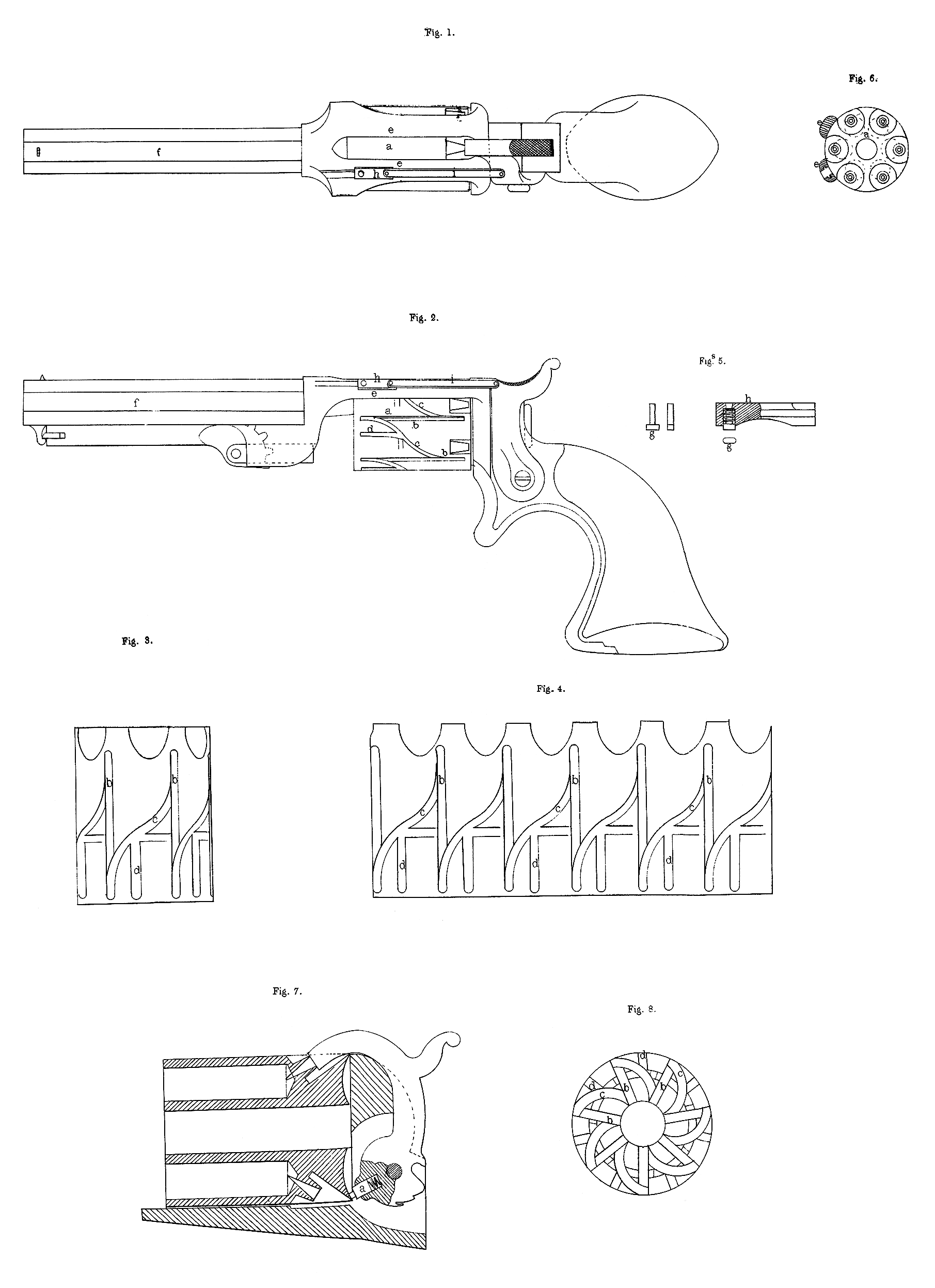
In the accompanying drawing I have shewn in several views the improvements which form the subject of this Invention. Fig. 1, shews in plan view, and Fig. 2, in side view, one of my improved pistols fitted with the novel arrangement for rotating the breech cylinder which constitutes the first head of this Invention. Instead of using a catch, which takes into a ring of ratchet teeth cut on the hind end of the breech cylinder, I groove the periphery of the breech cylinder in such a manner that a pin traversed by the hammer along the grooves will not only effect the desired rotation of the cylinder, but will also lock it when required. In the breech cylinder a, (which is represented as having six chambers) I cut a series of straight grooves by b, which extend nearly from end to end of the cylinder, and are equal in number to the chambers for receiving the charges. These grooves b, 5, are made parallel with the axis of the cylinder a, and they are connected together by means of diverging grooves c, running from near the forward end of one groove b, to near the hinder end of the next adjacent groove b. Between these straight grooves b, b, and running forward out of the curved grooves cy and parallel to the grooves b, are short straight grooves d, into which the traversing pin employed for driving round the cylinder a, enters when the loaded cylinder is required to be locked. The configuration and distribution of these grooves is best shewn at Figures 3, and 4, the former of which is a detached view of the breech cylinder on a somewhat enlarged scale, and the latter a diagram shewing the periphery of the cylinder as laid out flat. In order to ensure .the steady action of the traversing pin I provide a guide for the block which carries it in the frame of the arm by forming the frame as shewn at Figures 1, and 2, wherein e, e, is a continuation of the recoil shield carried over the cylinder a, (instead of under, as in my Patent of Twentieth June, One thousand eight hundred and forty-nine,) and supporting the barrel /, at its forward end. I would remark that this frame must be open in the line of the hammer, not merely to allow of the hammer descending upon the uppermost nipple to discharge the aim, but also to permit of the ready escape of the fire from the cap on the nipple; and for this latter reason I may find it convenient to form this part of the frame of two side straps, of sufficient strength to sustain the barrel firmly in position, and yet allow of one of the straps being slotted to form a guide for the block of the traversing pin. This pin, which in plan I prefer to approach an oval form, is shewn at g, (see the detached Figures 5,) and it is fitted loosely in a block A, which is secured by a connecting rod i, to the hammer, and by the movements of the hammer is slidden backwards and forwards in the guide formed by the frame e, (see the cross section Fig. 6). Surrounding the pin gy and enclosed in a recess made in the block h9 to receive it, is a helical spring, which gives the pin a tendency to stand out below the under face of the block h, and bearing against the periphery of the breech cylinder. I have already stated that the grooves b, c, and d, are formed to receive this pin, which runs therein for the double purpose of rotating the cylinder to bring up the successive charges, and of locking the cylinder when it is required to be stationary on its arbor. It will be understood that so long as the pin is confined to either of the grooves b, the breech cylinder will be quiescent, and that it is by the traverse of the pin in the diverging or curved groove c, that an axial motion is imparted to the cylinder. In order to induce the pin to enter the diverging groove when drawn back by the hammer an obstruction to the backward traverse of the pin is raised in the grooves b, at the point where the curved grooves respectively enter the grooves b, and thus the pin is guided out of the groove b, into the groove c. This obstruction is produced by raising the floor of the groove b, at the point mentioned, so that a slanting shoulder taking the curve of the groove c, will be presented to the receding pin. As, therefore, the pin is compelled to move in a line parallel with the axis of the cylinder by reason of its block sliding in the guide formed in the frame e, and as it cannot in its backward movement pass down the straight groove b, it will bear against the obstructing shoulder and the edge of the groove c, in a line therewith, and thereby drive round the cylinder until the next succeeding straight groove b, is brought into a line therewith, at which time a fresh chamber will be brought into a line with the barrel. This groove b, the pin will then enter by rising up an incline at the termination of the curved groove, and as the hammer falls back to the position of “ whole cock ” the pin will run to the end of its course. It should be remarked that the forward movement of the pin in the grooves b, is not retarded by the obstruction above mentioned, as an incline is made to permit of the easy passage of the pin over it. When the cylinder is required to be locked for carrying the arm safely the hammer is drawn back until the pin has reached a position in one of the diverging grooves opposite to a straight groove d; it is then allowed to fall forward, and the pin will be carried into the groove d, and lock the cylinder. To allow of the free rotation of the cylinder for the purpose of bringing the chambers severally under the plunger by which the cartridge is driven “home,” a ring of inclined planes is made by chamfering away a portion of one side of the grooves c, and the planes are so situated that when the hammer is thrown back at “ half cock ” the position of the pin will correspond to the position of the inclines; these inclines will, therefore, provide a means for the escape of the pin from the grooves, and thus the cylinder will be free to turn on its arbor to bring up the chambers, as required, for the purpose of charging the same.
A modification of the mode just described of effecting the rotation of the breech cylinder by the traverse of a pin in grooves formed in that cylinder is shewn at Figures 7, and 8. Fig. 7, shews the cylinder detached, and provided with radial grooves, and grooves which diverge laterally at its rear end; and Fig. 8, shews the cylinder in longitudinal section, with a pin a, for rotating it carried by the hammer. The pin is fitted into a recess formed in the inner end of the hammer, and it is kept in contact with the breech cylinder by a coiled spring contained in the recess. The end of the cylinder is hollowed out (see Fig. 8,) to suit the arc described by the traversing pin when rocked by the backward and forward motions of the hammer. With the exception of rocking instead of traversing in a right line, the action of the pin is the same as in the former-described arrangement. Similar provision is made for the transference of the pin from the radial grooves 5, to the curved grooves c, and also for the locking of the cylinder by the pin entering intermediate grooves d. There is likewise provision made for preventing the pin from interfering with the free rotation of the cylinder when the hammer is at half cock by employing a ring of inclined planes, as before, for raising the pin out of the grooves.
Having now described my Invention, and the manner of carrying the same into effect, I wish it to be understood that under the above in part recited Letters Patent I claim,—
First, the general arrangement of parts, as above described, for effecting the rotation of the breech cylinder.
Secondly, I claim the rotating and the locking of the breech cylinder, by. a traversing pin working in grooves formed on the periphery or rear end of the cylinder, as above described.