
Britain 743
Double and Single Action Lockworks
LETTERS PATENT to James Webley, of Birmingham, in the County of Warwick, Manufacturer, for the Invention of “ Improvements in the Construction of Repeating or Revolving and other Pistols and Fire-arms.”
Sealed the 29th September 1853, and dated the 29th March 1853.
PROVISIONAL SPECIFICATION left by the said James Webley at the Office of the Commissioners of Patents, with his Petition, on the 29th March 1853.
I, James Webley, of Birmingham, in the County of Warwick, Manufacturer, do hereby declare the nature of the said Invention for “ Improvements in the Construction of Repeating or Revolving and other Pistols and Fire-arms ” to be as follows :—
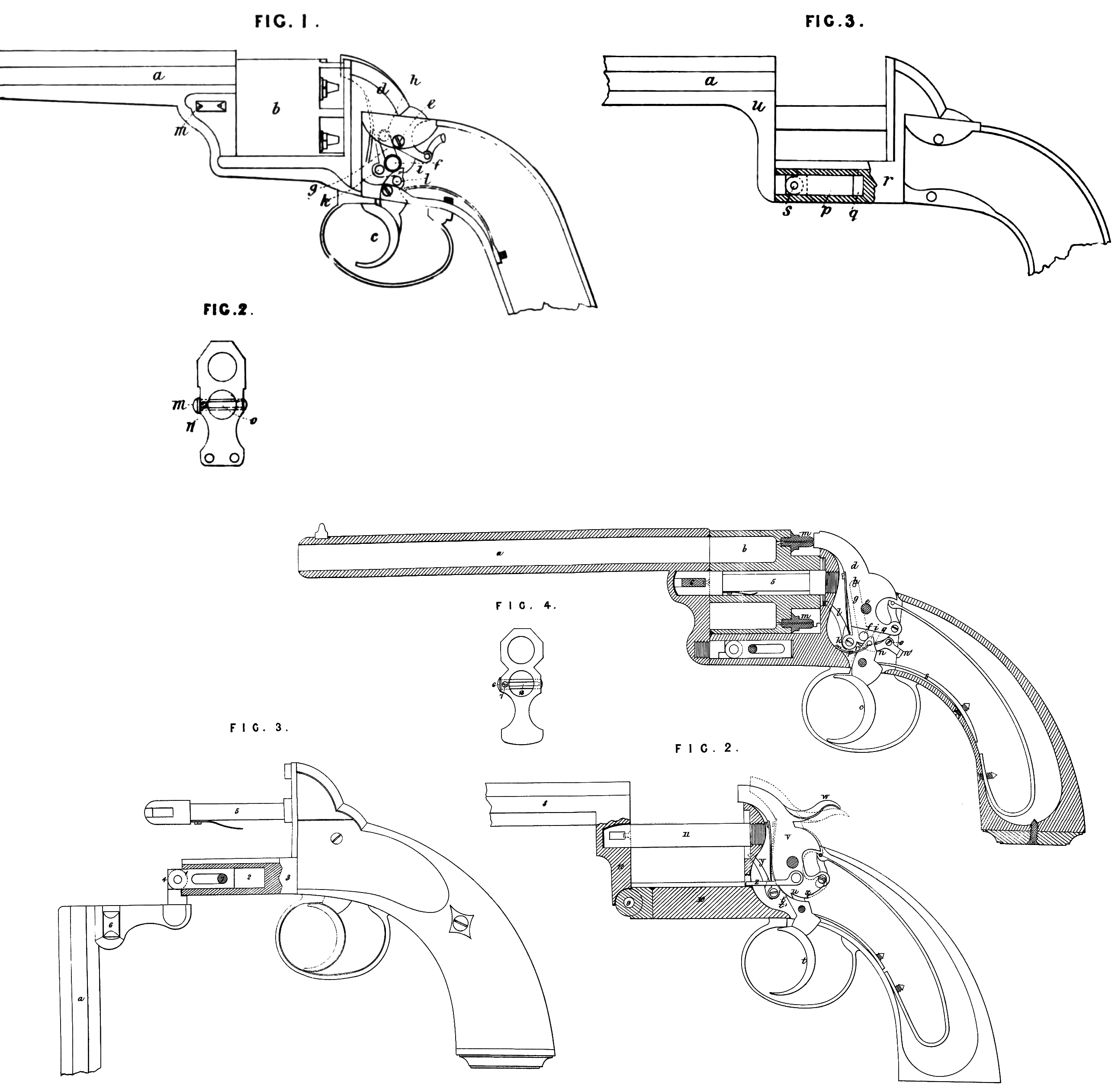
Fig. 1, represents a side view of a repeating pistol made according to my Invention, a, is the fixed barrel, and b, the revolving chamber containing the detonating barrels. One of the said improvements consists in the method of engaging and disengaging the trigger c, from the cock or hammer d; the said hammer cZ, is of the form represented in the drawing, and turns upon the centre e; /, is a pin or stud formed on the end of the spring </, (shown in dotted lines,) the said spring being attached to the back of the hammer or cock d, at the point h; the said pin or stud/, conies through a hole in the said hammer or cock, and the end of the said pin or stud, which is bevilled off or inclined, projects on the near side of the said hammer or cock; the head i, of the trigger c, bears against the back of the pin/, and on pressing the said trigger c, the said hammer or cock is raised until the head i9 of the said trigger c, escapes under the said pin /, when the hammer or cock d, falls and discharges the pistol. On removing the finger from the trigger c, the head i, passes over the inclined face of the pin /, and, pressing back the said pin, resumes the position represented, when the pin /, is again shot forwards by its spring h, and the head of the trigger 1, engages behind it. The arm by which the revolution of the chamber 5, is effected is attached to the hammer at Jc; and the arm, which acts as a stop to arrest the chamber 5, at the proper point, is attached to the trigger c, at l. The said arms, as well as the main spring, are omitted in the drawing, in order that the construction of the hammer d, and trigger c, may not be concealed.
Another improvement consists in the method of preventing the bolt m, which fastens the barrel ay in its place, from being wholly withdrawn ; this consists of a screw 7?. (see Fig. 2,) the end of which enters the groove 0, made in the edge of the said bolt, but not continued to the end thereof; the bolt m, can only be withdrawn till the end of the said screw comes in contact with the end of the groove 0, when the further motion of the said bolt m, is arrested.
Another improvement consists in the method of connecting the barrel with the body of the pistol. The lower side of the barrel 0, (see Fig. 3,) is provided with a jointed pin p, sliding in a cylindrical hole q, in the frame r, of the pistol; by withdrawing the barrel a, until the joint s, is external to the hole q, the said barrel a, may be turned down upon the said joint s. The said barrel is held in the position represented in the drawing by a bolt similar to that represented in Fig. 2; and the pin p, is prevented from being withdrawn wholly from the hole q, by a similar bolt and screw. The axle t, of the revolving chamber also enters a hole in the end u, of the said barrel.
SPECIFICATION in pursuance of the conditions of the Letters Patent, filed by the said Janies Webley, in the Great Seal Patent Office, on the 29th September 1853.
TO ALL TO WHOM THESE PRESENTS SHALL COME, I,
James Webley, of Birmingham, in the County of Warwick, Manufacturer, send greeting.
WHEREAS Tier most Excellent Majesty Queen Victoria, by Her Letters Patent, bearing date the Twenty-ninth day of March, in the year of our Lord One thousand eight hundred and fifty-three, in the sixteenth year of Her reign, did, for Herself, Her heirs and successors, give and grant unto me, the said James Webley, Her special licence that I, the said James Webley, my executors, administrators, and assigns, or such others as I, the said James Webley, my executors, administrators, and assigns, should at any time agree with, and no others, from time to time and at all times thereafter during the term therein expressed, should and lawfully might make, use, exercise, and vend, within the United Kingdom of Great Britain and Ireland, the Channel Islands, and Isle of Man, an Invention for “ Improvements in the Construction op Repeating or Revolving and other Pistols and Fire-arms,” upon the condition (amongst others) that I, the said James Webley, by an instrument in writing under my hand and seal, should particularly describe and ascertain the nature of the said Invention, and in what manner the same was to be performed, and cause the same to be filed in the Great Seal Patent Office within six calendar months next and immediately after the date of the said Letters Patent.
NOW KNOW YE, that I, the said James Webley, do hereby declare the nature of the said Invention, and in what manner the same is to be performed, to be particularly described and ascertained in and by the following statement thereof (that is to say):
Figure 1, represents, in vertical longitudinal section, a repeating or revolving pistol, in which some of the improvements constituting my Invention are introduced, a, is the fixed barrel, and b, the revolving chamber, containing the barrels in which the detonation of the gunpowder is effected. One of my said improvements consists in the method of engaging and disengaging the trigger c, from the cock or hammer d; the said hammer tZ, is of the form represented in the drawing, and turns upon the centre e. /, is a pin or stud formed on the lower end of the spring g, (shown in dotted lines,) the said spring being attached to the distant side of the hammer or cock d, at the point h; the said pin or stud f conies through a hole in the said hammer or cock, and the end of the said pin or stud, which is bevilled off or inclined, projects on the near side of the said hammer or cock d; the head i, of the trigger c, bears against the back of the pin / and on pressing the said trigger c, the said hammer or cock is raised until the head i, of the said trigger c, escapes under the said pin f when the hammer or cock cZ, falls and discharges the pistol. On removing the finger from the trigger c, the head i, of the said trigger returns over the inclined face of the pin/, and, pressing back the said pin, resumes the position represented in the drawing; the pin/, is again shot forward by its spring g, and the head 2, of the trigger engages behind it. The arm Z, by which the revolution of the chamber b, is effected, is attached to the hammer at l\ and a stop to arrest the chamber at the proper point is jointed to the top of the trigger. When it is wished to be able to raise the cock or hammer from the nipples w, by a partial pull of the trigger, and to leave it in that position till by a further pull of the trigger it is raised further and disengaged so as to discharge the pistol, (that is to say,) to be able to “ half-cock ** the said cock or hammer eZ,) I add a lever ??, of the form represented, turning upon the centre 0, and pressed against the under side of the hammer by the spring p. If the trigger c, be so far pressed as to bring the tooth <7, past the end r, of the lever n, and the pressure then be removed from the said trigger, the said end of the lever n, will engage behind the said tooth q, and prevent the falling of the cock or hammer d. By pressing the trigger c, until its head i, escapes under the stud/, the spring s, resting on a shoulder of the trigger, as represented, (and by which the return motion of the trigger is effected,) will be so far raised as to bear against the end n\ of the lever n, and disengage the end r, from the tooth q; the hammer d, will then not be obstructed in its fall by the lever n.
Another of my improvements in the construction of repeating pistols is illustrated by Figure 2, and consists of another method of effecting the “ half-cocking ” of repeating or revolving fire-arms. In carrying this part of my Invention into effect I make the head t\ of the trigger t, of the pointed form represented, and I make a tooth u, on the under side of the hammer or cock v, of such a form that when by the partial raising of the hammer effected by applying the thumb at w, the said head t\ engages behind the said tooth w, and cannot be disengaged therefrom by pressure on the trigger t. By pulling back the hammer v, till the head t\ of the trigger t, engages behind the shoulder tT, of the said hammer, the said hammer is brought into a position from which it can be released by pressure upon the trigger t; for the shape of the shoulder x, permits of the escape of the head t\ of the trigger t, from behind it by pressure on the said trigger. y9 is the arm by which, on raising the cock v, the revolving chamber is turned; and z9 the stop by which the said chamber is stopped at the proper place for the discharge.
Another of my improvements consists in the method of connecting the barrel a, Figure 1, with the frame of the pistol; this part of my Invention is represented in Figure 1, but will be best understood by reference to Figure 3. A jointed pin 1, is attached to the lower side of the barrel a\ the said pin 1, slides in a cylindrical hole 2, made in the frame 3, of the pistol. By withdrawing the barrel a, until the joint 4, is external to the hole 2, the said barrel may be turned down upon the joint 4, and the revolving chamber removed from the axis 5. The barrel is held in its position by a bolt 6 ; and the said bolt 6, as well as the pin 1, are prevented from being wholly withdrawn in the manner herein-after described. I sometimes modify the last-described portion of my Invention in the manner represented in Figure 2; that is to say, I connect the barrel 8, by a joint 9, to the frame 10, of the pistol, the end of the axis 11, of the revolving chamber being bevilled off at top as represented, for the purpose of permitting the turning of the part 12, upon the joint 9.
Another of my improvements consists in the method of preventing the bolt 6, Figures 1 and 3, which fastens the barrel a, in its place, from being wholly withdrawn; this consists of a screw 7, (see Figure 4,) which represents in front view that part of the frame attached to the barrel a; the end of the said screw enters the groove 13, made in the edge of the said bolt, but not continued to the end thereof; the bolt 6, can only be withdrawn till the end of the said screw comes in contact with the end of the groove 13, when the further motion of the said bolt 6, is arrested. I apply this method of preventing the withdrawal of the pin or bolt 1, Figure 3, to whatever parts of pistols and other fire-arms the same maybe applicable.
Another of my improvements consists in making the middle portion of the axle on which the revolving chamber of revolving or repeating fire-arms turns of a square or prismatic figure, as represented at 5, Figures 1 and 3. By this improvement the oil and dirt from the ends of the axle work into the middle part 5, of the axle, where they accumulate w ithout interfering with the working of the chamber. Although I have described and represented my several improvements in connection with pistols only, yet I apply the same to such other fire-arms as they are or may be applicable to.
Having now described the nature of my said Invention, and the manner in which the same is to be performed, I wish it to be understood that I do not limit myself to tlio precise methods of carrying my Invention into effect herein described, and represented in the accompanying drawing, as the same may be varied without departing from the nature of my said Invention. But I claim,—
Firstly, the action or mechanism for the lock of a revolving or repeating pistol or other fire-arms herein described, and represented in Figure 1, of the accompanying drawing.
Secondly, applying the action or mechanism herein described, and represented in Figure 2, to repeating or revolving pistols and fire-arms.
Thirdly, the methods herein described and represented in Figures 2 and 3, of connecting the barrel of repeating or revolving pistols and fire-arms to the frames thereof; also the method of preventing the complete withdrawal of the bolts used in fire-arms, illustrated in the Figures 1 and 3. as well as in Figure 4.
Lastly, making the middle ])art of tlio axles of revolving or repeating fire-arms of a square or prismatic figure.
In witness whereof, I, the said James Webley, have hereunto set my hand and seal, this Twenty-fourth day of September, in the year of our Lord One thousand eight hundred and fifty-three.
JAMES WEBLEY. (l.s.)