
US 627966
UNITED STATES PATENT OFFICE.
BUKARD BEHR, OF BENDLIKON, SWITZERLAND.
IMPROVEMENT IN REVOLVING FIRE-ARMS.
SPECIFICATION forming part of Letters Patent No. 627,966, dated July 4, 1899. Application filed June 2, 1898, Serial no, 682,355. (No model.)
To all whom it may concern:
lie it known that I, Burkard Behr, a citizen of the Russian Empire, residing at Bendlikon, near Zurich, Switzerland, have invented certain new and useful Improvements in Revolvers or Pistols, of which the following is a specification.
This invention relates to pistols or revolvers; and it consists, substantially, in such features of improvement as will hereinafter be more particularly described.
While a pistol or revolver constructed in accordance with my invention is adapted for all the uses or purposes of an ordinary hand firearm, it is the object of my invention to provide an arm particularly adapted for the use of cyclists in discharging blank and flash cartridges to scare away dogs arid other animals that may be in the path or road traveled by the machine. To this end I construct the chamber for the cartridges with flat sides, which are flush with the sides of the remaining parts of the firearm, said chamber being substantially a box pivoted in such manner that by successively turning the same by hand to a position corresponding to one hundred and eighty degrees the cartridges in each half of the chamber can be discharged through the barrels of the arm in the ordinary way. The purpose of thus constructing the firearm is to render the same perfectly flat or without side enlargements or projections, so that it can be carried more conveniently in the pocket and also so that it can be conveniently packed in an ordinary bicycle tool-box without occupying as much space as an ordinarily-constructed revolver.
The invention also has for its object to provide simplified devices for successively exploding the cartridges on each side of the chamber and also to otherwise simplify the construction of a pistol or revolver intended for the present purposes.
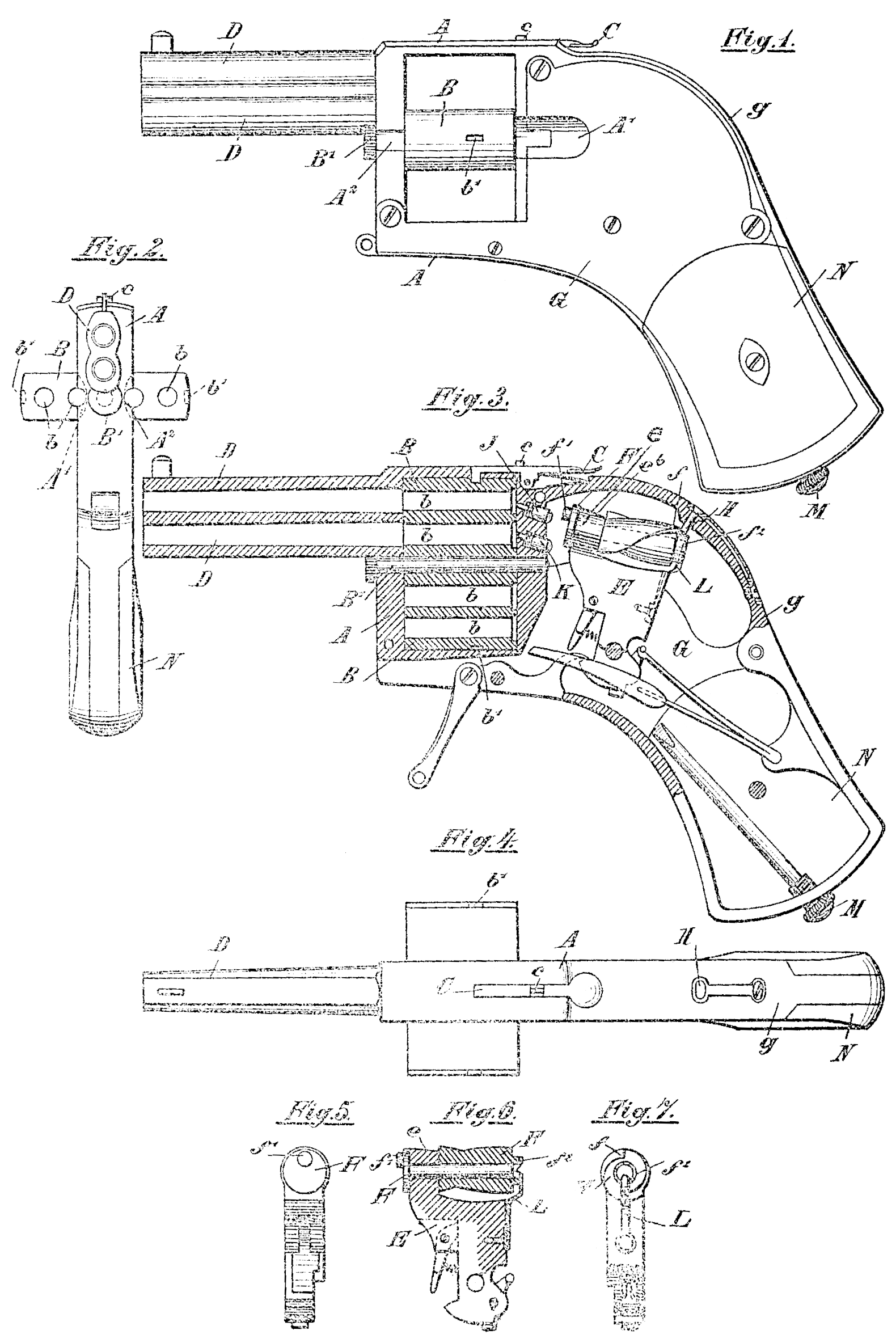
In the accompanying drawings, Figure 1 is a side elevation of the pistol; Fig. 2, a front view. Fig. 3 is a vertical longitudinal sectional view, and Fig. 4 a. plan view. Figs. 5, 6, and 7 are end and sectional views of the cock with a peculiar revoluble striking-bolt mounted thereon.
The pistol, as in a revolver, consists of a frame A, in which, however, in place of the cylinder there is mounted a flat box 3, provided with four cartridge-chambers b, Figs. 2 and 4, pivoted on a removable pin B’. The thickness of this lox is equal to that of the frame A, so that when closed it fits flush everywhere in the frame A— that is to say, no part projects out of the frame. The box B is secured in the closed position in the frame A by means of a spring-lever C, Figs. 3 and 4, which springs into a recess b’ formed on each side of the box. A back sight c is also mounted on the lever C. When the box 3 is in the frame A in the closed position, it lies with the cartridge-chambers l of its upper half in front of the barrels D of the pistol, so that the two cartridges can be successively fired off. This successive firing of the two barrels and cartridges is effected by a peculiarly-constructed cock. This cock carries on its head a roller F, mounted in the eye e of the part E and provided on the rear end with curved grooves or screw-spirals f, Figs. 4 and 5, extending in the form of a thread. In the rear or back g of the lock-casing G a spring-pin H is so arranged that when the cock is moved back to be set the roller F is engaged by the said pin H, which enters the spiral groove of the roller until the eye e passes under the pin H and lifts the same out of the groove f. In order that the said pin may be thus lifted, the outer surface of the said eye is inclined upwardly and forwardly, as shown at e^6, so that by the time the pin reaches the highest point of the incline it has been sufficiently elevated or raised for the purpose desired. As, however, the pin H is only vertically movable and is laterally immovable, the roller F when the cock is set thus, receives a partial rotation, by hereby a projection f’ on the cock, which, for instance, previously lay opposite the upper firing-pin J, is now brought opposite the under firing-pin K, and therefore strikes the latter on the firing of the pistol, and thus discharges the lower cartridge. On the next setting of the cock the roller F, in the manner hereinbefore described, is again, revolved a half-revolution, so that the projection f’ comes opposite the upper striking-bolt J, and the upper cartridge is fired off. When two cartridges have thus been discharged, the box is rotated one hundred and eighty degrees on its axis B’ after the spring-lever C has been pressed to release the box, and the other half of the box, with its cartridges, is than brought into position for discharging.
in order that after the partial revolution has taken place the roller F may not during the springing forward of the cock be turned back again by means of the pin H, the said roller F is provided at its rear end with a ring of ratchet-teeth f^2, in which a pawl L, Figs. 5 and 6, snaps at each forward revolution of the roller, and thus prevents the roller making a backward rotation.
The remaining parts of the lock mechanism may be of any suitable form of construction and in the example shown are made exactly as in other revolvers and are well known. In order to load the box B, it is either entirely withdrawn from the frame A after the pin B’ has been pulled out or the box is turned into the horizontal position shown in Fig. 2, in which the cartridges are easily inserted into the box from the rear. The insertion or ejection of the middle cartridges— that is to say, the cartridges lying next to the pin B’, on which the box rotates— is rendered possible by means of a recess or groove A’, formed in the frame A, Figs. 1 and 2.
A suitable appliance in the form of a screwdriver M, screwed into the handle N, accompanies the pistol.
Having now particularly described and ascertained the nature of my said invention and in what manner the same is to be performed,I declare that what I claim is—
1. A hand-firearm or revolver having two or more barrels, and provided with a pivoted cartridge-chamber flush or even with the frame of the arm, a firing-pin for each barrel, a hammer or cock provided with an eye or bearing at its upper forward edge, a spirally grooved cam-roller mounted on said hammer and partly fitting and turning within said eye, and having a projection for engaging the firing-pins, a spring-pressed device entering the grooves of the roller to turn the latter on the backward movement of the hammer, and also engaging the outer surface of the eye when the hammer is back, to thereby disengage said device from the grooves, and a pawl engaging the rear end of the roller to prevent back turning of the same on the forward movement of the hammer.
2. A hand-firearm or revolver provided with two or more barrels, and a firing-pin for each barrel, a rotatable cartridge-chamber adapted to be brought to different positions to successively explode the cartridges therein, a hammer or cock provided with an eye, a roller supported in said eye having a projection for engaging the firing-pins, and provided with spiral grooves, a spring-pressed device entering the grooves to turn the roller on the backward movement of the hammer, and also engaging the outer surface of the eye when the hammer is back, to thereby disengage said device from the grooves, and a pawl engaging the rear end of the roller to prevent back turning of the same on the forward movement of the hammer.
3. A hand-firearm or revolver provided with two or more barrels, and a firing-pin for each barrel,a rotatable cartridge-chamber adapted to be brought to different positions to successively explode the cartridges therein, a hammer or cock provided with an eye or hearing at its upper forward edge, having its outer surface inclined upwardly and forwardly, a rollers supported in said eye having a projection for engaging the firing-pins, and provided with spiral grooves, a spring-pressed device entering the groove to turn the roller on the backward movement of the hammer, and also engaging the highest point of outer surface of the eye when the hammer is back to thereby disengage said device from the grooves, and means engaging the roller to prevent back turning of the same on the forward movement of the hammer.
In testimony that I claim the foregoing as my invention I have signed my name in presence of two subscribing witnesses.
BURKARD BEHR.
Witnesses:
A. M. Lieberknecht,
Elise Edel.