
US 459874
UNITED STATES PATENT OFFICE.
KAREL KRNKA, OF PRAGUE, AUSTRIA-HUNGARY.
REVOLVNG-MAGAZINE FIRE-ARM.
SPECIFICATION forming part of Letters Patent No. 459,874, dated September 22, 1891. Application filed September 28, 1888, Serial No. 286,665, (No model.)
To all whom it may concern:
Be it known that I, Karel Krnka, a subject of the Emperor of Austria, residing at Prague, Vinohrady, Kingdom of Bohemia, Austria-Hungary, have invented a new and useful Improvement in Fire-Arms, of which the following is a specification.
My invention relates more particularly to improvements in small-arms, and especially to pistols or carbines, whereby the arm can be charged not only as a single-loader, but also by means of a revolving magazine, which can be readily inserted and removed, as desired, and whereby, also, the cartridge is exploded in the barrel itself and not in the revolving cylinder, as is the case with revolvers constructed in the usual manner.
The objects of my improvements are, first, to provide a Small-arm which can be quickly and continuously fired, and in which the whole strength of the gas is used for propulsion of the bullet, while in the usual revolvers much of it escapes between the barrel and the revolving cylinder; second, to provide for automatically throwing out the shells of the cartridges after each shot; third, to provide for firing from a magazine containing a number of cartridges, (for instance, six or more,) which magazine is easily replaced by a fresh one when empty; fourth, to provide for charging single cartridges directly into the barrel; fifth, to prevent accidents from the circumstance that revolvers must be charged long before their being used, while in my new system the revolving magazine can be instantly thrown into its chambers and fired off, so that the arm need not be charged until immediately before being used; sixth, to provide for fixing the breech-bolt in its extreme forward position by turning a Screw-plug into a small groove, so that it can be instantly opened again; seventh, to provide for great efficacy and Smooth exterior of the arm combined with simplicity of construction and facility of dismounting and mounting.
The invention is fully illustrated in the accompanying drawings, in which—
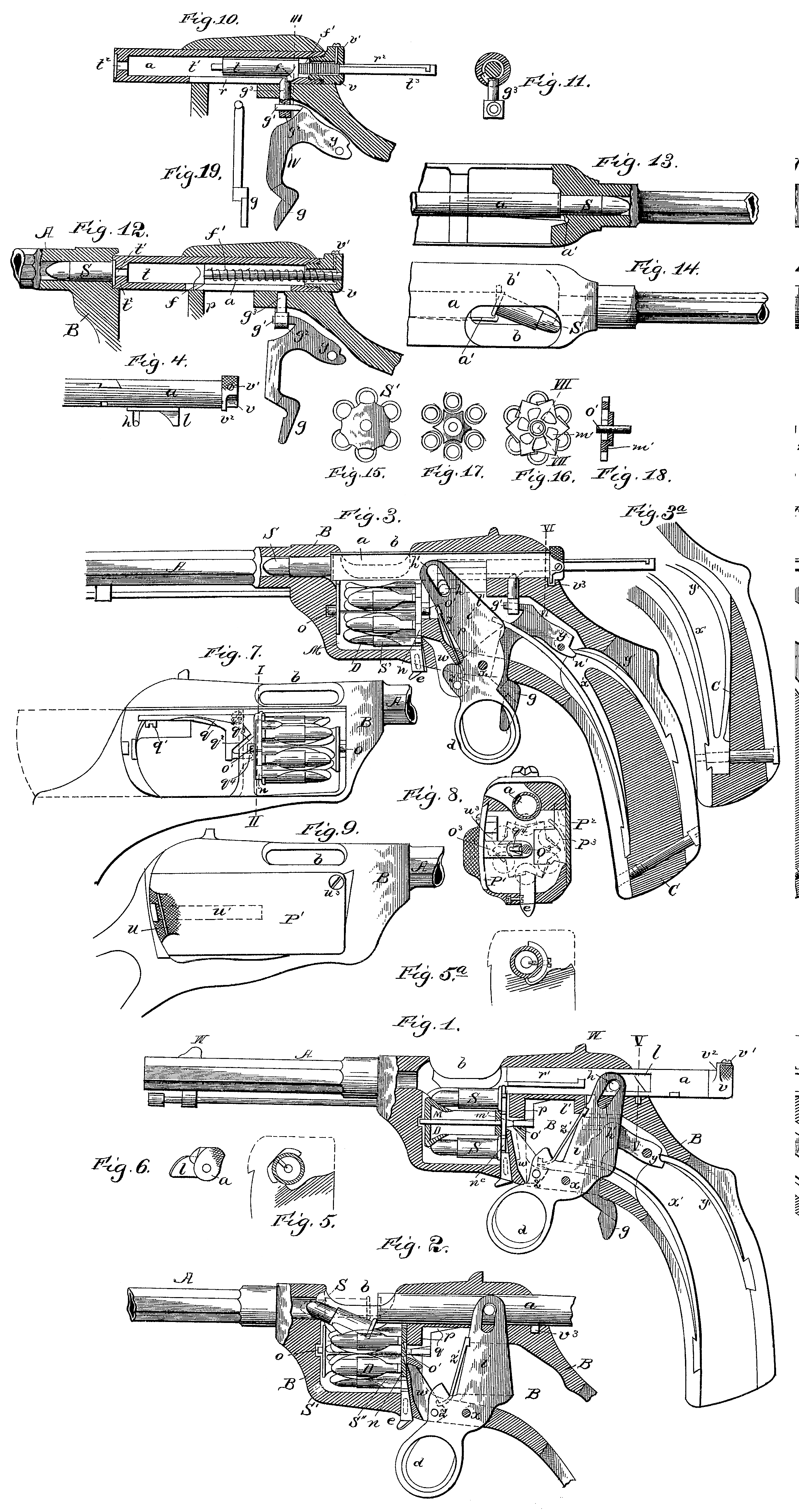
Figure 1 is a longitudinal section of the arm, the breech-bolt being in its extreme rearward position. Fig. 2 shows the bolt in the act of being pushed forward from the position shown in Fig. 1 and charging the upper cartridge from the magazine into the barrel. Fig. 3 is a longitudinal section of the arm, the breech-bolt being in its extreme forward position, having just charged the upper cartridge into the barrel, but the firing-pin being retained by the sear. Fig. 3^a shows a modification for uniting the two mainsprings into a single one. Fig. 4 is a top view of the breech-bolt, the firing-pin being inside. Fig. 5 is a transverse section of the breech-bolt through the line V V in Fig. 1. Fig. 5^a is a similar view through the line VI VI in Fig. 3. Fig. 6 is a rear end view of the breech-bolt. Fig. 7 is a side view of the arm, showing the right side of the body or frame open. Fig. 8 is a transverse section of the body or frame through the line III in Fig. 7. Fig. 9 is a side view of the arm, showing the right side of the body or frame closed. Fig. 10 is a longitudinal section of the breech-bolt in the position shown in Fig. 3. Fig. 11 is a transverse section through the line III IV in Fig. 10. Fig. 12 is a longitudinal section of the breech-bolt at the moment of firing. Figs. 13 and 14 are top views illustrating the extraction of the shell after firing. Figs. 15 to 18 are detail views of the rotating magazine. Fig. 19 is a detail view of the trigger-lever.
Similar letters refer to similar parts in the several views.
A represents the barrel, B the solid frame or body of the pistol, and C the handle or stock. The barrel may be screwed into the Solid frame, or it may be made in one piece, as indicated in the drawings. The body or frame contains two chambers, which are divided by a transverse wall p. The side walls of the body or frame are closed by two doors P’1 and p^2. I call P’ the “right-wall door” and P^2 the “left-wall door.” The front chamber is for holding the revolving magazine D. The rear chamber contains the ring-lever d i, with its pawl Q, and the trigger g , with its sear g^3. The mainsprings X’ and Y’ are contained in the stock or handle C.
The body or frame B is bored out in a continuation of the line of the barrel to contain the breech-bolt a. Through a hole b the extracted shells are automatically thrown out. This hole also serves for the introduction of single cartridges if they are used instead of the magazine. In any case the cartridges are not exploded in the revolving cylinder, as they are in the usual revolvers, but really in the barrel itself, and the whole strength of the gas is used for the propulsion of the bullet.
The upper cartridge of the revolving magazine lies vertically under the axis of the barrel, just behind the same and in front of the bolt a. The cartridges S S are kept in the cylinder D of the magazine by semi-cylindrical springs which are fastened to the said cylinder D and open outwardly, each spring being cut off in the middle and cut in on the front end, so as to form two elastic wings, which keep the cartridge properly in its place in the magazine, the cartridge being arranged with its rim toward the rear plate or ratchet n and with its head on the inclined front of the magazine-cylinder D, as shown in Fig. 1 and in Figs. 15 to 18. When the ring d is pulled back, the bolt a moves forward and inserts the upper cartridge into the barrel, as shown in Fig. 2. Fig. 3 shows the extreme rear position of the ring d.
The upper cartridge is inserted into the barrel, and the bolt a is locked and secures the cartridge. The extractor a’, Figs. 13 and 14, is sprung over the rim of the cartridge, and Will push the shell backward when, after firing, the ring d is pushed forward. The pin h of the bolt a slides in the slot h’ of the lever i, and this slot forms an inclined connection, so as to facilitate the turning of said bolt a when its tooth or projection l is pulled toward the transverse wall p and moves from the position shown in Figs. 1 and 2 to the position shown in Fig. 3, whereupon the pin h, which in Figs. 1 and 2 is horizontal, will turn downward at an angle of about forty-five degrees, and the tooth l will lock into a groove l’, so that in firing the pressure of the gas is transmitted to the frame or body by the tooth l.
The breech-bolt a is a hollow cylinder and incloses the hammer and firing-pin, which consists of a spindle having an enlarged piston-like portion t, which forms the hammer and which corresponds with the interior dimensions of the bolt and slides snugly therein, a forward extension t’ of smaller dimensions, which constitutes the firing-pin proper, and a rear extension t^3, also of smaller dimensions. In the front end of the bolt a is an orifice to permit of the protrusion of the firing-pin t’. The rear end of the bolt a is closed by a screw-plug v, having a central orifice, in which the rear extension t^3 works after the manner of a piston-rod, Surrounding the piston-rod or extension t^3 is a coiled spring f’, one end of which bears against the screw-plug v and the other against the rear shoulder of the enlarged portion or hammer t, so as to have a tendency to keep the firing-pin pressed forward.
On the under side of the hammer i is a tooth or lug f, which works in a slot r in the bolt a in order to preserve the rectilineal motion of the hammer and firing-pin, and which also engages with the sear, as hereinafter, described.
The trigger g is pivoted at y and is engaged by the spring y’, as shown in Figs. 1 and 3. The ring-lever d i is pivoted at x and is engaged by the spring x’, as also shown in said Figs. 1 and 3. The nose g’ of the trigger g engages with an eye g^3 at the lower end of the sear g^3, which works vertically through an opening in the frame or body B, with its upper end in the slot r and in line with the tooth or lug f, either in front of it, as in Figs. 3 and 10, or in the rear of it, as in Fig. 12. When the bolt a is moved forward to the position shown in Figs. 3 and 10, the engagement of the sear g^3 with the tooth or lug f arrests the forward movement of the firing-pin, compresses the spring f’ between the hammer t and the screw-plug v, and cocks the arm, so as to be ready for firing. When the trigger is pulled, the sear releases the firing-pin, and the expansion of the spring drives it forward and explodes the cartridge. No gas can escape between the barrel and the revolving cylinder, as is the case with the usual revolvers.
The screw-plug v is provided with an eccentric. projection v^2, which engages with a recess v^3 of the body or frame when the bolt is in its extreme forward position and the screw-plug is turned downward about sixty degrees. A small screw v’ projects inwardly from the screw-plug v into the slot r^2 of the piston-rod t^3. Another slot r’ is provided in the bolt a for the ejector-pin b’, the operation of which is well known. This slot has a short turn of ninety degrees at its rear end, owing to the circumstance that the bolt a turns in its extreme forward position for the purpose of locking into the recess l’, as has been explained. The two other slots rand r^2 for the same reason have such short turns of ninety degrees at each end because of the sear g^3 and of the small screw v’ and for the extreme positions shown in Figs. 1, 3, and 12.
For the purpose of introducing the revolving magazine into its chamber the sliding door P’ is drawn back into the position indicated in Fig. 7 by dotted lines, Fig. 9 being its position when closed and kept firmly in its place by a side spring u.
The revolving magazine has two pins o o’ at the center, which slide in two horizontal grooves extending to the center of the frame or body. The magazine-chamber is of such size that the magazine can be easily introduced. When the magazine is inserted and the sliding door P’ shut, the beak q^4 of the spring q q^2 q^4 bears against the rear pin o’ of the magazine and keeps it in its place, so that it can be turned on its pins o and o’. The spring q q^2 q^4 is fastened on the top and inside the rear chamber to the frame or body by the screw q’. The right sliding door P’ has a projection u^3, which prevents it from being drawn out too far in one or the other direction. If this door is drawn completely back, the projection u^3 acts as a wedge, lying between the spring q and the body or frame, and it pulls the spring-shoulder q^2 down upon the partition-wall p at q^3. This prevents the sliding door from being drawn out completely. By this action q^4 is pressed down and the Center pin o’ of the revolving magazine can slide in and out, so that the magazine may be introduced or taken out entirely. As soon as the sliding door P’ is closed, Fig. 9, the magazine can only rotate. The inside wing P^3 of the left door keeps the cartridges in their respective places upon the body of the magazine. The rear plate m’ of the same forms a ratchet, with as many ratchet-teeth as there are cartridges in the magazine. The magazine, as shown in the drawings, contains six cartridges, and the ratchet-plate m’ six teeth. The pawl w oscillates on its pin z, which is mounted on the lever d i, which at the same time turns on the horizontal axis x. A spring z’ is fastened to the side of the lever i and presses with its free end on the pawl w, which is guided in an inclined slot of the partition-wall p. The pawl w acts on the ratchet-plate m. when the ring d is pushed forward after the empty shell has been extracted and in the last moment before said ring arrives into its extreme forward position. By this action of the pawl w the ratchet is turned so that the next cartridge of the magazine arrives at the top. The stopper e is held by a side pin or screw, so as not to fall Out, and is guided in a vertical slot in the body or frame. The ring d at the same time pushes the stopper e upward, as shown in Fig. 1 and the periphery of the ratchet m’ is shaped so that at the same moment a groove presents itself to the stopper, as shown in Fig. 8 in dotted lines, the stopper being kept in it by the ring d, as shown in Fig. 1. The ring d is kept firm in this extreme position by the mainspring. By this device each pushing of the ring forward in the position indicated in Fig. 1 brings a fresh cartridge before the breech-bolt. The next pulling of the ring d backward inserts that cartridge into the barrel, as indicated in Fig. 2. If the operator puts his finger inside the ring, the charge is fired at once. If he puts his finger before the ring without touching the trigger, the position shown in Fig. 3 will be the result, which position can be used for aiming. It can be secured by turning the screw-plug v to the left in the position indicated in Fig. 5, so that no firing is possible. On pulling the ring d forward the automatic extraction of the shell is produced, as indicated in Figs. 13 and 14. If the magazine is empty, the operator draws the right-hand door back, as indicated in Fig. 7, and throws the magazine off by a slight movement of the arm. It requires very little exertion to throw off the empty magazine and to introduce a new one into the front chamber. Then the door P’ is closed and the arm is ready for firing. There is no need of charging the revolving cylinder anew and of throwing out the empty shells, as this is the case with the usual revolvers; but still, if time allows it, the empty magazine can be filled with cartridges and can be used again. Should the said movements not be carried out properly, or in case of inexact shape of cartridges, it may happen that a cartridge will not enter into the barrel without difficulty. A similar quick movement of the whole arm, holding the opening b in front, will bring the defective shell out at once, and then regular firing can proceed again.
The purpose of the two mainsprings x’ and y’ has been explained. For the purpose of reducing the number of pieces I unite these two springs in some cases, as indicated in Fig. 3^a. The wood handle is in one piece and kept in place by a screw at the end of the handle.
I am aware that prior to my invention breech-loading arms were made with breech-bolts, ring-levers, and triggers. I therefore do not claim such a combination, broadly; but
What I do claim as my invention, and desire to secure by Letters Patent, is—
1. In a breech-loading fire-arm, the combination, with the frame having the magazine chamber grooved on its front and rear faces, of the revolving magazine-chamber having the axial pins o o’, adapted to fit said grooves, and a catch or beak q^4 for engaging the pin o’ and preventing its lateral displacement, substantially as set forth.
2. In a small breech-loading arm, the combination of a revolving cartridge-magazine carrying its cartridges S S in elastic beddings S’ S”, which are fastened around a light metallic cylinder. D, and which open outwardly, so that the cartridges can be easily put into or pulled out from these beddings for the purpose of being charged by the breech-bolt into the barrel, substantially as described.
3. The combination, in a small breech-loading arm, of the ratchet m’, forming the rear plate of the revolving magazine, with its pawl w and stopper e, the former being mounted and oscillating upon the ring-lever d i and being pressed forward into engagement with the ratchet by the spring z’, while the stopper e is held by the ring d in engagement with stop-notches in the magazine-cylinder in the extreme forward position of this ring, both for the purpose of revolving automatically and keeping fast the cartridge-magazine, substantially as set forth.
4. The combination, with the revolving magazine having the pins o o’, of an elastic pin-holder q q^2 q^4 and the sliding door P’, and projections u^3, carried by said door in line With and adapted to engage and withdraw the pin-holder for the purpose of clearing the horizontal rear slot for the pin o’ when the door P is open and keeping automatically the pin o’ in its place when the magazine is introduced and the door P’ shut, substantially as set forth.
5. The combination, with the magazine chamber and the revolving magazine, of the door P^2, carrying the wing P^3, which latter engages the magazine to assure the proper position of the cartridge in its beddings, substantially as shown, for the purpose specified.
6. The combination, with the frame having the doors P’ P^2 and the magazine, of the breech-bolt having the screw-plug v, the ring-lever d i engaging the same, the firing-pin carried by said bolt, the sear engaging said pin, the trigger connected with the sear for releasing the pin, the pawl w, carried by the said lever and engaging the magazine, and the stopper e, situated in line with said lever and also engaging the magazine, substantially as set forth.
In witness whereof. I have hereunto set my hand in presence of two witnesses.
KAREL KRNKA.
Witnesses:
L. Vojaiet,
Adolf Fischer.