
US 476591
UNITED STATES PATENT OFFICE.
ISRAEL N. ARCHBOLD, OF RIDGE FARM, ILLINOIS.
REVOLVING FREARM.
SPECIFICATION forming part of Letters Patent No. 476,591, dated June 7, 1892. Application filed July 30, 1891, Serial No. 401.225, (No model.)
To all whom, it may concern:
Be it known that I, Israel N. Archbold, a citizen of the United States, residing at Ridge Farm, in the county of Vermillion and State of Illinois, have invented certain new and useful Improvements in Repeating Fire-arms, of which the following is a specification.
My invention relates to that class of repeating fire-arms in which a revolving cartridge-cylinder is journaled in the opening at the breech or base of the barrel; and it consists, in general, in the provision of a revolving cylinder or breech-block whose face is longitudinally grooved or channeled to form a circular series of longitudinal sockets or open chambers, a flange at one or both ends thereof, the flange at the fore-end being bored to correspond with the position and number of said sockets and also to suit the caliber of the gun, and an independent cartridge-holder adapted to be mounted in numbers in a carrier chain or belt and successively seated in said sockets or open chambers by means of the usual revolving action of the cylinder, the construction, arrangement, and operation of all of which will be fully hereinafter described, and particularly pointed out in the claims.
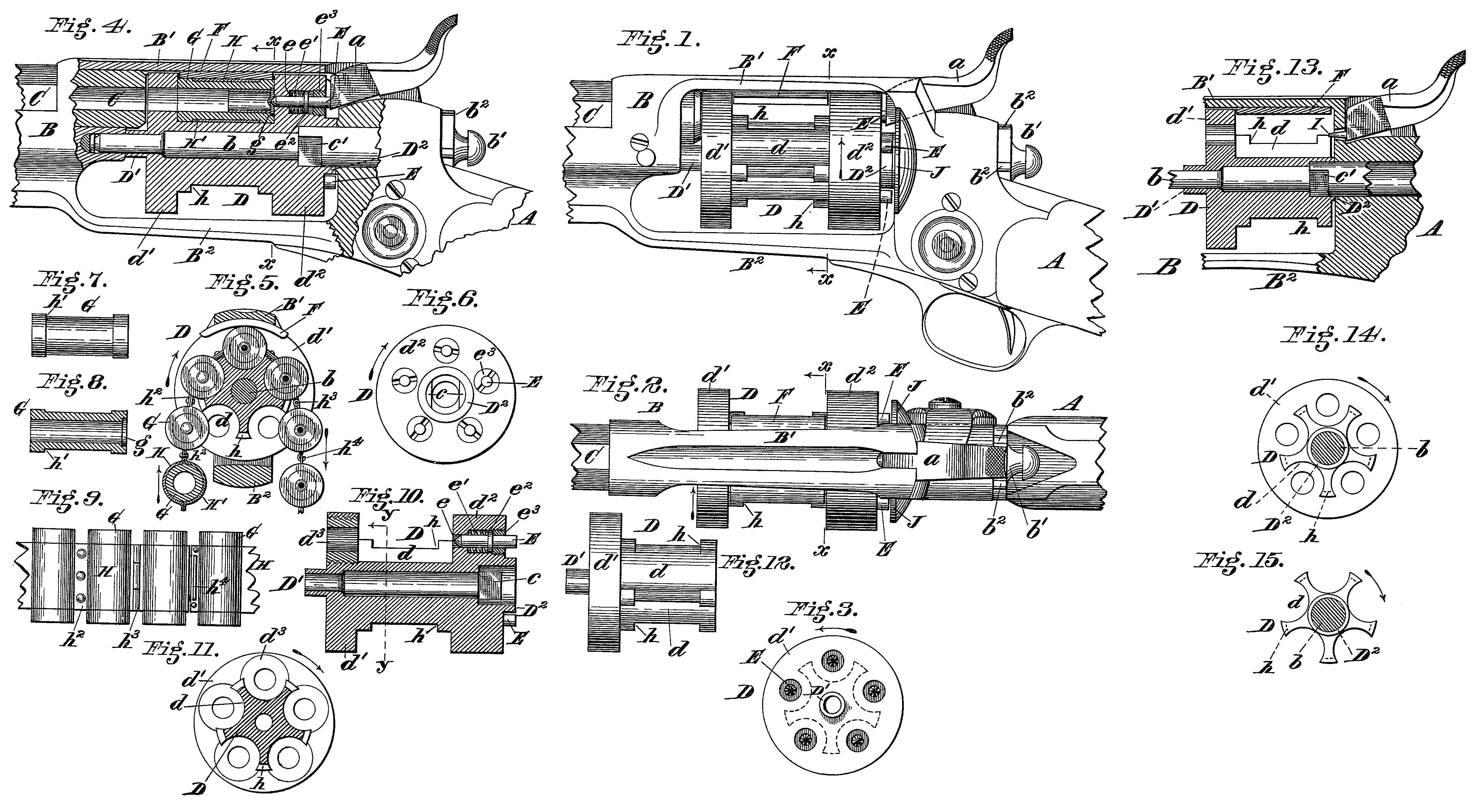
In the accompanying drawings, Figure 1 is a broken (full-size) longitudinal elevation of an ordinary revolving-cylinder rifle, showing one form of my improved open-chambered cylinder in operating position therein; Fig. 2, a plan of the parts shown in Fig. 1; Fig. 3, a fore-end view of my open-chambered cylinder, shown in said Figs. 1 and 2; Fig. 4, a broken elevation similar to Fig. 1 and of the same parts, except that part thereof is broken open and in section on an approximately central longitudinal line to show my cylinder more clearly, a cartridge-holder being seated therein with an empty shell succeeding a firing operation; Fig. 5, a transverse sectional elevation on line x x, Fig. 4, looking forward (as per arrow at top of said line) and showing my improvements complete, a cartridge-holder carrier chain or belt being fed through the breech-chamber of the gun by my open chambered cylinder, one of the cartridge holders (the lowermost one to the left) being shown in cross-section and empty, the two preceding holders above having unexploded cartridges therein and the next preceding holders, beginning with the uppermost one, (that in line of fire) having the empty shells of exploded cartridges therein; Fig. 6, a rear end view of the form of cylinder shown in the first four figures, illustrating the manner of arranging and mounting the firing-pins, which are designed for use with an ordinary firing-hammer; Fig. 7, a longitudinal elevation of one I of my improved cartridge-holders especially adapted for use in connection with my open chambered cylinder; Fig. 8, a central longitudinal section of the holder shown in Fig. 7; Fig. 9, a broken longitudinal plan of a series of my cartridge-holders mounted in chain or band form for quick continuous firing in my open-cylinder gun; Fig. 10, a central longitudinal Section of the form of open cylinder shown in the previous figures, except that the firing i pin is retracted into its normal position (ready for the blow from the raised hammer) and bushings provided in the forward flange in line with the several longitudinal grooves or cartridge-holder sockets, so as to facilitate the boring or other finishing work in the construction of the latter; Fig.11, a transverse section on line y y, Fig. 10, looking forward as per arrow at top of said line; Fig. 12, a longitudinal elevation of another form of my open-chambered cylinder, in which construction the rear flange of the cylinder shown in previous figures is omitted; Fig. 13, a broken sectional elevation showing the form of cylinder seen in Fig. 12 mounted in a gun whose hammer is provided with a firing-pin located on its firing-pin at a point for engagement with a central-fire cartridge; Fig. 14, a rear end view of the cylinder shown in Figs. 12 and 13, its central axial shaft being in section; and Fig. 15, a similar view to Fig. 14, but of another form of my open-chambered cylinder, in which construction the flanges at both ends are omitted.
A represents the gunstock; B, the frame, which is constructed with the usual opening at the breech for the revolving charge-cylinder and a chamber in the rear of the latter for the lock or firing mechanism, and C the gun-barrel. These parts are all constructed as usual, or in any suitable manner common to revolving-cylinder arms, and will need no detailed description herein, except that a is the firing-hammer, and b the spindle b or center-pin, upon which the cylinder is axially mounted.
In the drawings i have shown my improvements as applied to an ordinary Colt rifle; but it is obvious that they are equally well adapted to any other make of similar revolving-cylinder arms.
D represents my improved cylinder mounted (in said Colt pattern) on the spindle so as to revolve there with, corresponding and engaging flat portions c and c’, which are constructed within the central bore of the cylinder and on the spindle, respectively, to form a coupling for such mutual action.
In the rim of the head b’, constructed at the outer end of spindle b, are cult the usual notches b^2, which are engaged by the automatic bolt mechanism (not shown, as it is old and well known) to hold the spindle and cylinder immovable, except when it is desired that they shall revolve, as customary.
d represents each one of a circular series of longitudinal deep grooves or concavities in the face of cylinder D, registering in turn with the barrel C, and d’ d^2 are two peripheral flanges, one at either end the cylinder, flange d’ being at the fore-end and flange d^2 at the rear. This double-flanged form is designed to suit the cylinder to the plane-ended hammer. (Clearly shown in Figs. 1, 2, and 4.) Flange d’ is bored at intervals to correspond in arrangement and number with said grooves d, and also to suit the caliber of the cartridge used in the gun; or it may be fitted with bored bushings d^3, as shown in Figs. 10 and 11, the latter form being either screwed or brazed in place, as desired. It may be preferable to provide the flange d’ with the said bored bushings, as such construction enables the ready longitudinal boring and final finishing of the concavities d without the use of a special tool to work perpendicularly to the surface thereof, which would be necessary in the final cutting and finishing of the grooves d when the said holes, which are of less diameter than said grooves, are bored in flange d’ direct, as shown in Figs. 3, 4, and 5.
E represents each one of a circular series of firing-pins mounted in chambers e in flange d^2, so as to register with the respective grooves d and the holes in flange d’, as shown in Figs. 3, 4, and 10, the thickness of such flange d^2 being greater than that of the flange d’, so as to properly accommodate said firing-pins. Chambers e are each graduated or constructed in three diameters, the inner diameter being the shallowest and forming an aperture for the proper passage of the point of said firing-pin, the next diameter being sufficiently large to contain an expansion spiral spring e’, which surrounds said firing-pin and exerts an outward pressure on its collar e^2 to retreat or retract its point completely within the flange d^2, so that said point shall not normally project, even to the very slightest degree, beyond the inner face of said flange, and the outer or greatest diameter being screw-threaded to accommodate the detachable threaded cap or plug e^3, through whose central opening the outer end of the firing-pin projects beyond the outer face of said flange for receiving the blow from the hammer. The cylinder has the usual fore hub D’ and rear hub D^2, and is preferably intermittingly controlled (as customary in revolving firearms) by an ordinary gun-lock composed of the hammer, trigger, and the accompanying mechanism for revolving it and holding it in position for the firing operation.
In Figs. 12, 13, and 14 I have shown my cylinder with the fore flange d’ only and a very short rear hub D^2, the rear ends of the grooves or sockets d being thereby open for the special purpose hereinafter described.
In Fig. 15 I have shown the manner in which I may construct my cylinder with both flanges d’ and d^2 omitted, the purpose being also fully hereinafter described.
On the under side of the upper bar or ligament B’ of the gun-frame I attach a curved guide-plate F, whose length is slightly less than that of the width of the space between the flanges d’ and d^2, so that it may project downward within said space intermediate said flanges, as clearly shown in Figs. 1, 2, 4, 5, and 13.
G represents an independent cylindrical cartridge holder or chamber made of steel or other suitable material and of a length and diameter to snugly fit within either of side sockets or grooves d in the cylinder D, as shown in Figs. 4 and 5. The holder G is bored to suit the caliber of the cartridge used therein and also to correspond with that of the gun-barrel, and a countersunk recess or shoulder g is provided in its rear end to accommodate the usual flange or rim of the cartridge, thus forming a suitable seat therefor to prevent frictional or other unintentional contact and effectually avoid accidental firing from such source.
Cartridge-holders Gare preferably mounted in series and at regular intervals apart in carrier chain or belt form, as shown in Figs. 5 and 9, whereby they are flexibly linked or held together, and thereby properly adapted to be fed into and through the breech-opening in the frame B by means of and engagement with the cylinder D, immediately in rear of the gun-barrel.
H and II, respectively, represent the upper and inner webs or divisions of the belt or chain between which the holders G are mounted, and whereby they are coupled together in Series at equal distance apart to correspond with the length of the arc between centers of adjoining sockets or grooves d in the cylinder, so that when the first holder in the chain shall have been introduced into or seated in one of the said sockets (the uppermost socket to the left of the center, the one that is next in line of fire being the proper one, as can be readily seen by reference to Fig. 5) the succeeding holders shall seat themselves in the succeeding sockets in rotation as the cylinder is turned a portion of a revolution after each firing operation, the curved plate F, with its rounded edge, serving as a suitable means to guide and effectually set each holder in its turn in said sockets, and also prevent its outward play or release when the cartridge is fired.
h represents each one of a series of notches or recesses in the cylinder, cut in the ribs or partitions, separating one socket d from the other and designed to accommodate the ligaments or joints in the carrier chain or belt, composed of the divisions H and H’, both the construction and application of which are clearly seen in Fig. 5.
I have shown the several divisions H and H’ of the chain or belt as being set in a recess h’ between slightly-flanged ends of each holder, so that the outer face of both said divisions shall lie in the same plane as the said flanges, and thereby present an even surface to be properly seated in the sockets of the cylinder.
When the webs or divisions H and H of the cartridge-carrier are made of leather or other similar flexible material, the joints between adjoining holders are riveted, as shown at h^2 in Figs. 5 and 9; but when said divisions are made of sheet metal or the like they are flexibly coupled together by hinge-joints, as shown at h^3 in said Figs. 5 and 9, or hook and eye, (chain-link form,) as shown at h^4 in both said figures.
In the operation of my improved cylinder and cartridge-carrier the first holder of the latter is fed or set into the uppermost open chamber or socket of the cylinder to the left, as before stated, and them the hammer is raised. The raising of the hammer simultaneously causes a partial revolution of the cylinder in the usual manner, so that when it has reached full-cock said cylinder has rotated the proper distance to bring said first cartridge-holder to register with the barrel and properly locked at the breech in line of fire. By the simple pulling of the trigger the hammer falls and the cartridge explodes, as usual, the result of the operation just described being fully shown in Fig. 4, wherein a spent cartridge is seen with the firing-pin in contact and the hammer down. The succeeding movements are precisely the same, the simple act of cocking the gun causing the usual simultaneous and intermittent rotation of the cylinder, which in turn draws or feeds the cartridge-carrier into the breech-opening at one side of the gun to present each successive cartridge in line of fire, and simultaneously passing that portion of the carrier containing the empty shells from the gun at the opposite side of said breech-opening in the frame. Thus two motions only are necessary to operate my gun, viz: The cocking of the hammer loads it and simultaneously clears it of the spent cartridge, and the pulling of the trigger fires it. One motion in a double-action gun— viz., that of pulling the trigger simply— would suffice to both load and fire my gun, as is clearly obvious. As soon as the hammer is released from contact with the firing-pin (after the result of the said operation seen in Fig. 4) the said firing-pin is automatically and positively, retracted by the outward expansive pressure of spring e’, thus withdrawing the pivot thereof fully within the flange d^2, so as to prevent any obstructing contact whatever with the carrier or its contents, except when the hammer falls for the firing operation. The immediate retreat of the firing-pin on the raising of the hammer enables the ready release of the carrier from the cylinder as it passes outward to the right pursuant to the firing operations, the outward swinging, together with the gravity of the carrier and its contact with the lower bar B^2 of the frame, readily causing the release of the holders from the sockets after firing actions. The falling of the hammer of course follows each feeding or drawing-in operation of the cylinder and carrier. The arrows adjacent the several parts described indicate their direction of movement clearly. The flanges upon both ends of the cylinder constitute suitable side guides for the cartridge-carrier, whereby it is properly drawn or fed into the gun and passed outwardly therefrom, and may therefore be considered the preferred form, especially for the plane character of the contact end of hammer shown in Figs. 1, 2, and 4; but when a hammer having a central fire pin or point I constructed directly thereon, such as that shown in Fig. 13, is used the rear flange d^2 is omitted, and the usual laterally-projecting lugs or cheeks J form the rear guides for the inward and outward passage of the carrier. The central fire-pin operates through a small aperture i in the gun-frame, as usual. It is obvious that the latter form of cylinder, having the rear flange omitted, is equally well adapted to what are known as the “concealed-hammer” or “hammerless” guns, the detail description and construction of which Will not be necessary herein, as the central firing-pin is practically the same in all and may be in the shape of a needle, bolt, or other forms common to repeating arms.
The form of cylinder shown in Fig. 15 is one in which both flanges are omitted, and it is therefore well adapted for use in small arms having a short opening in the frame. It is constructed with the same semicircular side sockets or open chambers d for the reception and seating of the cartridge-holders, and also with the notches or recesses h (shown in dotted lines in said Fig. 15) for seating the joints or ligaments in the carrier chain or belt, as hereinbefore described.
Each of the notches h in all the patterns of cylinder herein shown and described serve as an auxiliary in properly guiding and seating the respective cartridge-holders in the several cylinder-sockets while the cylinder revolves, and also maintaining said holders in place for the advancing movement of the cylinder or other movements of the gun, and especially so when both flanges d’ and d^2 are omitted, as in Fig. 15.
In the general use of my invention herein carriers holding, say, the usual “forty rounds” of cartridges, may be preferred; but it is obvious that they may be made in greater or less lengths to contain any number of cartridges in accordance there with and consistent with their weight and caliber and the draft-power of the cylinder-revolving lock mechanism and also the service in which the gun is used; or said carriers may be made in belt form or end less, in which case a link in each one should be open to render it readily attachable and detachable to and from the piece.
Among the many important advantages and special features of my invention herein may be cited the following:
The open-socketed cylinder and independent cartridge-holders reduce the heating of the parts in firing to a minimum, thereby enabling the piece to be fired exceedingly rapid and for an unlimited length of time, one carrier after another being readily fed into and passed across the breech-opening without necessarily lowering the gun from the shoulder or ceasing the action of the lock. The cylinder cannot positively become heated owing to its wide-open Sockets and the fact that each cartridge-holder is independent, and thus forms a firing shell or cylinder for its particular cartridge only, and it passes from the gun immediately after its charge is fired.
The loaded cartridges can be very readily placed in the holders of the carrier and their empty shells just as readily removed after firing in any suitable manner. The loaded carriers being entirely separate and distinct from the gun and the open-socketed cylinder not being in any wise adapted to contain a charge unless one of my holders containing a loaded cartridge or the carrier containing loaded holders is in place therein, it is certainly quite obvious that my construction is absolutely safe both in and out of action. The gun minus the loaded holder-carrier can thus be handled freely and laid around loosely, if desired, without danger of accidental or other unintentional discharge. It cannot therefore and is not loaded or charged unless a charged holder or holder-chain is in place in the cylinder, and said holder or holder chain is not placed in the gun except when it is intended to use and fire it.
The open condition of the cartridge-holder sockets from the face of cylinder facilitates the cleansing and inspection thereof at any time, and said cartridge-holders are just as readily cleaned and inspected.
The gun itself may be continued in constant use and charges fired therefrom so long as loaded carriers are supplied, which of course is unlimited, for the reason that while a carrier containing forty or more rounds is being fired another may be filled, or while several such carriers are being fired one that has already been fired may be rid of its empty shells and recharged. Thus the loading of a gun on my plan herein is very simple, expeditious, and practical.
The cylinder can be made so as to operate the cartridge holder or holders with any suit able lock and firing mechanism— that is, such lock and firing mechanisms as are adapted to cylinder or revolving arms.
Having thus fully described my invention, what I claim is—
1. In a repeating firearm, a revolving cylinder or breech-block whose face is longitudinally grooved or channeled to form a circular series of longitudinal sockets or open chambers therein, a flange at one or both ends thereof, the flange at the fore-end being suitably bored to correspond with said sockets and the caliber of the gun and the flange at the rear end fitted with firing-pins registering with said sockets, said cylinder being adapted to receive a cartridge-holder carrier drawn into the opening in the frame at the breech of the barrel by the intermittent rotation of said cylinder, and the cartridges fired in succession, substantially as herein set forth.
2. In a repeating firearm, a rotating cylinder having longitudinal semicircular furrows or grooves d on its surface to form chambers or sockets open at the side, the ribs between said grooves being each provided with a recess for the reception of the ligaments of a carrier-chain as it passes through the gun, substantially as herein set forth.
3. In a repeating firearm, a rotating cylinder having longitudinal semicircular open sockets or chambers d on its surface and a flange d’ at its fore-end, the latter being suitably bored to correspond with said sockets and the caliber of the gun, substantially as herein set forth.
4. In a repeating firearm, a rotating cylinder having longitudinal semicircular open sockets d and fore-end flange d’, the latter being fitted with a circular series of bushings d^3, corresponding in arrangement and number with said sockets and each having a central bore suited to that of the caliber of the gun, substantially as herein set forth.
5. In a repeating firearm, a rotating cylinder D, having a circular series of longitudinal semicircular open grooves or sockets d and a rear flange d^2, the latter being fitted with a circular series of firing-pins E, corresponding in number and arrangement with said socket, substantially as herein set forth.
6. In a repeating firearm, a cylinder D, having the longitudinal open sockets d and rear end flange d^2, the latter being fitted with firing-pins E, said firing-pins registering with the respective sockets d and mounted in graduated chambers e, each of such chambers containing expansion-springs bearing outwardly against collars on said pins, and a screw plug or cap e^3, substantially as herein set forth.
7. In a repeating firearm, a rotating cylinder D, provided with open sockets and a rear flange, firing-pins in the flange registering with the sockets, and a cartridge-holder carrier comprising a series of firing-shells in a flexible chain and adapted to be fed through the gun by means of the rotation of the cylinder, the bore of each firing-cylinder being provided at its rear end with a countersunk recess or shoulder for the reception of the cartridge, whereby the carrier may fit closely within the sockets of the cylinder, substantially as described.
8. In a repeating firearm, the combination, with the frame-bar B’ and the cylinder D, of a guide-plate F, mounted on said frame-bar B’, substantially as herein set forth.
In testimony of which invention I have hereunto set my had.
ISRAEL, N. ARCHBOLD.
Witnesses:
H. C. Elliott,
C. Wm. Davis.