
US 545528
UNITED STATES PATENT OFFICE.
ERNST PAUL, OF WIESBADEN, GERMANY.
IMPROVEMENT IN REVOLVING FIRE-ARMS.
SPECIFICATION forming part of Letters Patent No. 545,528, dated September 3, 1895. Application filed October 15, 1894, Serial No. 525,959. (No model.)
To all whom it may concern:
Be it known that I, Ernst Paul, a citizen of the Kingdom of Prussia, and a resident of Wiesbaden, in the Kingdom of Prussia, German Empire, have invented certain new and useful Improvements in Revolvers, of which the following is a specification.
The object of my invention is to provide an improved firearm which will also comprise a knife and serve as a thrust weapon; and the improvement consists generally in forming the butt-end of the pistol in two sections, one of which serves as a sheath for a knife, which may be at once thrown into position ready for use, and also to provide novel means for operating the blade by the single pressure of a button.
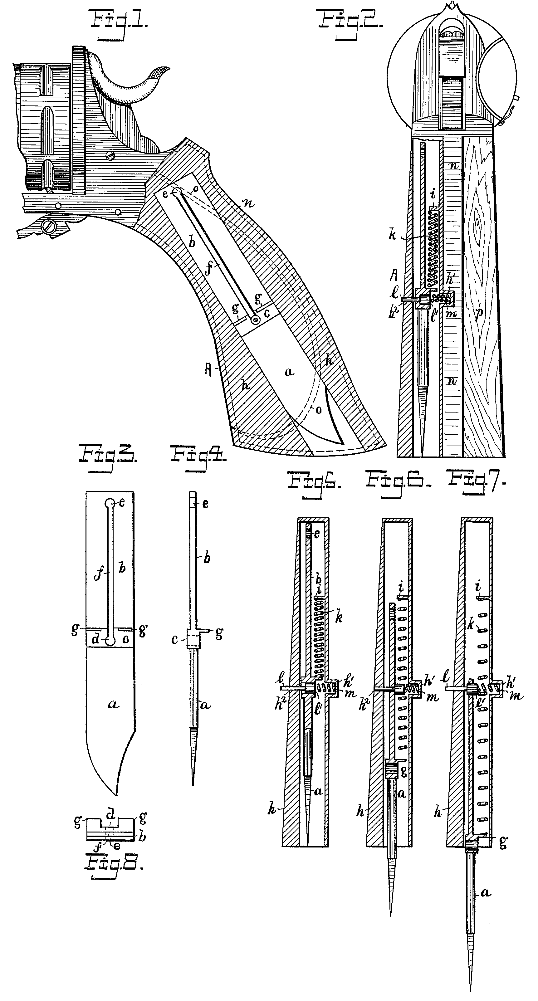
In the accompanying drawings, which illustrate the preferred form, construction, and arrangement of parts comprising my invention, Figure 1 is a side elevation of a revolver with the butt-sheath in longitudinal section; Fig. 2, an end elevation thereof, looking to the front in the direction of the revolver sights with the butt-sheath in transverse longitudinal Section; Fig. 3, a side elevation of the knife-blade detached; Fig. 4, a back edge view thereof; Fig. 5, a transverse longitudinal section of the butt-sheath with the knife inclosed and secured therein; Fig. 6, a similar view of the same with the knife projecting half its length from the sheath; Fig. 7, a similar view of the sheath with the knife un sheathed to the full length of the blade and secured in such position; Fig. S, a plan or top view of the blade with the slot and enlargements at the ends thereof shown by dotted lines.
The drawings represent my invention applied to what is generally known as a “Colt’s navy revolver,” with the butt A or the butt sheath h forming part of the same, as hereinafter described, shown in section to receive a knife-blade a, the upper half or handle end b of which is made flat and thin, with a division shoulder or thickness c between said knife-blade Cl, and the handle end b. A hole d, drilled through the shoulder thickness c, and a similar hole e at the upper end of the handle end b, are connected by a long narrow slot extending nearly the full length of the handle end b of the blade, and short stubs g upon one side of the blade project from the top edge of the thickness c upon either side of the slot f, and thus form the blade complete ready to be placed within the sheath h, and secured therein in the following described manner.
A small outwardly-projecting socket h’ and an inwardly-projecting stub i upon one side and a perforation h^2 upon the other side of the sheath in axial line with said socket h’ complete the sheath h ready to receive the above-described knife-blade and its operating connections. Two spiral springs k are arranged, one upon each side of the slot f in the knife-blade, to press or exert their tension between the stub upon the inner side of the sheath h and the stubs g, projecting from the top edge of the thickness c, thus to serve in firmly and truly pressing the blade out from the sheath with a quick forcible movement when it is released from the spanner l, which holds it therein. The spanner l is a short steel pin made to snugly fit the perforation h^2 in the sheath h, also to snugly fit the slot f of the blade, and having an enlarged hub l’ upon its inner end, which snugly fits the drilled holes d and eat the ends of the slot f of the blade, when they are respectively brought opposite the socket h’ in the side of the sheath h. The socket h’ holds a small spiral spring m’ which presses against the outer” end of the enlarged hub l’ of the pin l and tends to press the said pin l outwardly to project beyond the outer face of the sheath h when not otherwise acted upon, as shown in Figs. 5 and 7 of the drawings, and which is accomplished only when the knife is held within the sheath by means of a hub l’, engaging with the enlarged socket d in the middle of the blade, as shown in Fig. 5, and when the said hub l’ engages with the enlarged socket e at the end of the blade and in the respective ends of the slot?, as shown in Fig. 7, in which last-named position the blade is securely held to project its full length out of the sheath, and can only be pushed back again into the sheath by pressing upon the pin l until the enlargement l’ is pushed out of the socket e, and the blade being pressed against some unyielding substance permits the small end l of the pin to be moved in the slot f, as shown in Fig. 6, its full length, until the spring m. again forces the large end l’ of the pin l into the middle socket d in the blade and securely holds the blade within the sheath against the pressure of the springs k above described. The spring n is of sufficient strength to prevent the accidental movement of the pin l, when in the last-named position, by pressing with sufficient force upon the projecting end of the pin l, as in Fig. 5, and the blade will be released and the spring k will quickly force the blade out into the position shown in Fig. 7, and securely held by the pressure of spring m upon l, to force the enlargement l into the socket e when they shall come opposite each other, and hold the blade securely ready for use.
The knife becomes a powerful defensive weapon when the pistol is reversed, and the hand grasps the butt-end in such position that the knife will project forwardly from the clenched hand with the barrel of the pistol resting against and supported by the back of the forearm. Although my invention is shown as applied to a pistol, it may be similarly applied to the butt or handle of any small firearm; but it would be less convenient and also dangerous in its application to small arms to be handled by placing the butt to the shoulder without the employment of some safety attachment, readily suggested by one skilled in the art, as a screw-thread and nut upon the outer end of the pin l, to prevent the accidental discharge of the knife-blade from the butt-sheath while the latter is being held against the shoulder.
The exterior contour of the sheath h conforms to the shape of the half butt-piece p placed upon the opposite side, and both halves are made to conform to the shape of the steel frame-piece n, within which the elliptical spring o, of ordinary form, is placed for operating the lock mechanism in the usual way. The sheath half of the butt may thus at any time be removed and a butt-piece of any preferred material substituted therefor, or my attachment may be readily made to any revolving pistol by removing one of the side butt-pieces and substituting my sheath butt-piece of corresponding shape.
Either of the devices— that is, the revolver or the sheath-knife, having a handle adapted to conform to a revolver-butt section— may be used separately or together and thus constitute a new article of manufacture. The sheath-knife when separated from the revolver is complete and in every way a convenient practicable device for every-day use for the army, for the navy, and for the huntsman, and need not be applied to the revolver until it is required in time of special danger.
I am aware that a bayonet-knife has been applied fixedly to the butt or stock of a rifle or musket, to be inclosed therein when not in use, but the knife and its sheath are not a complete attachment adapted for separate use, as is my device, and although a fixed knife attachment is objectionable for ordinary use it becomes an important and useful adjunct in times of desperate resistance.
I claim as my invention and desire to secure by Letters Patent—
1. A knife attachment for revolver handles comprising a butt sheath, a knife blade having stubs g and a longitudinal central slot f, two spiral springs held within the sheath upon opposite sides of the slot to bear against said stubs, and a central spanner pin adapted to engage with the blade and hold it in either its open or its closed position, substantially as described.
2. A knife attachment for revolver handles comprising a butt sheath h, an end wise moving blade a, b, fitted within the sheath having a longitudinal slot f, and a stub g projecting from the side thereof, a spiral spring k, interposed between the sheath and handle to push the blade outwardly, and a spanner pin l adapted to fit the groove in the blade and interlock with either end thereof, substantially as described.
3. A knife attachment for revolver handles comprising a butt sheath h, having an outwardly projecting socket h’, and an inwardly projecting flange i, a blade a, b, having a slot f, and end notches d, e, and actuated by a spring k and a spanner l, spring m, to fit the socket h’ and act upon the spanner, substantially as described.
In testimony that I claim the foregoing as my invention I have signed my name in presence of two subscribing witnesses.
ERNST PAUL.
Witnesses:
W. Haupt,
Chas. H. Day.