
US 570145
UNITED STATES PATENT OFFICE.
GIOVANI BATISTA PITTAVINO, OF NEW YORK, N.Y.
IMPROVEMENT IN REVOLVING FIRE-ARMS.
STOCK AND BARREL, EXTENSION FOR PSTOLS OR REVOLVERS.
SPECIFICATION forming part of Letters Patent No. 570,145, dated October 27, 1896. Application filed November 14, 1895, Serial No. 568,885, (No model.)
To all whom it may concern:
Beit known that I, Giovani Batista Pittavino a citizen of France, and a resident of New York city, in the county of New York and State of New York, have invented certain new and useful Improvements in Guns, of which the following is a specification, reference being had to the accompanying drawings, forming a part thereof, in which similar letters of reference indicate corresponding parts.
This invention relates to rifles or similar guns, and particularly to target-rifles, and the object thereof is to provide a device of this class which may be taken apart and put together in compact form and for purposes of transportation, &c.; and the invention consists in the construction, combination, and arrangement of parts hereinafter described and claimed.
The invention is fully disclosed in the following specification, of which the accompanying drawings form a part, in which—
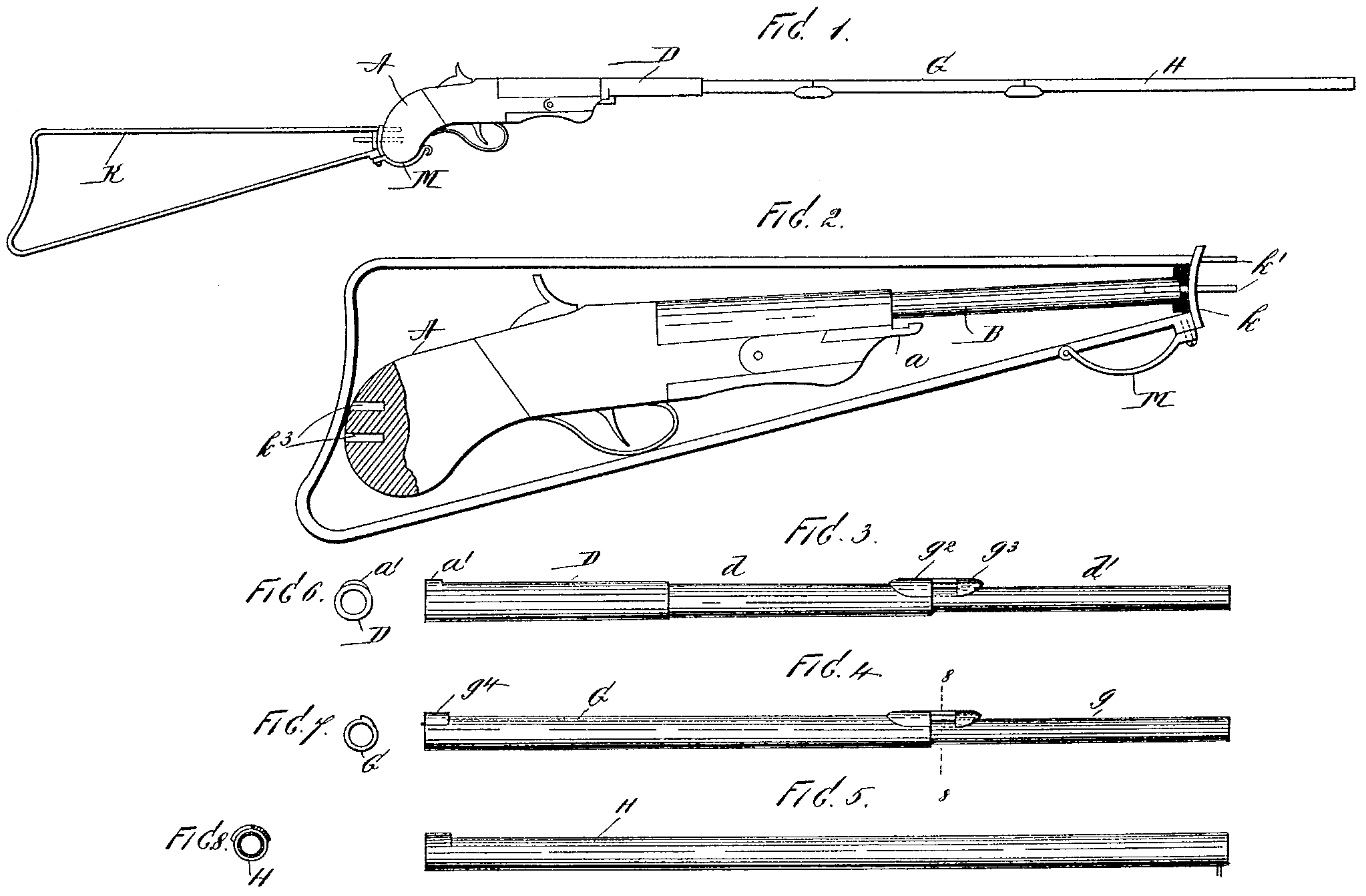
Figure 1 is a side view of my improved rifle; Fig. 2, a side view with the barrel portion thereof detached and also the stock, said stock and the frame, including the lock mechanism and a portion of the barrel, being placed together for transportation or packing purposes. Figs. 3, 4, and 5 represent separate sections of the barrel. Figs. 6 and 7 represent the inner ends of the sections shown in Figs. 3 and 4, and Fig. S is a transverse section on the line 8 8 of Fig. 7.
In the practice of my invention I provide a grip-piece A, in which the lock mechanism is placed, and said grip-piece is provided with one section of the barrel, as shown at B in Fig. 2.
The barrel of my improved rifle is composed of three sections independent of the section B, the first of which is shown at D, Fig. 3, the second at G, Fig. 4, and the third at H, Fig. 5. The inner end of the section D is shown in Fig. G and the inner end of the section G in Fig. 7.
The section D is provided with two extensions d and d’ and the section G with an extension g, and these parts are placed together in the following manner: The larger end of the section D is passed over the section B, which is secured to the frame, and then by turning said section the parts are locked together by a bayonet-joint composed of two parts, one of which is connected with the frame A, as shown at C, and the other with the inner end of the section D, as shown at a’.
The part a’ of the bayonet-joint which unites the section D with the section B consists simply of a segmental lug which is adapted to be turned into engagement with a shoulder or projection formed on the part a.
The section G is connected with the section D by being slipped over the extension d’ thereof, and said parts are connected substantially in the same manner as the sections D and B by means of a bayonet-joint composed of two parts, the first of which, g^2, is secured to the extension d of the part D and is provided with a forwardly-directed extension having a shoulder g^3, and the second of which consists of a lug or shoulder g^4, formed on the part G, which is adapted to operate in connection with the shoulder g^3; and the part II of the barrel is connected with the part G. by being slipped over the extension g and secured in place by means of a bayonet-joint similar to that which unites the parts D and G.
As thus constructed it will be seen that the separate sections of the barrel may be formed and securely united so as to constitute a single barrel, and the means by which said sections are united render the barrel as strong and rigid as though formed of a single piece. I also employ a stock which is composed of wire, as shown at K, Fig. 1, said Wire being bent into the usual form and provided at its inner end with a segmental piece k, from which project two pins k’, which are adapted to enter slots k^3, formed in the grip-piece A, and secured to the lower side of the inner end of the shoulder-piece is a segmental spring-arm M, which is adapted to be swung into position beneath the end of the grip-piece A, as clearly shown in Fig. 1, and which, when the parts are separated, may be folded backward into the position shown in Fig. 2. By means of this construction the stock may be connected with or detached from the frame or grip-piece whenever desired, and, as will be Seen, when the parts are separated, as shown in Figs. 2, 3, 4, and 5, they may be packed in compact form, so as to be placed in a small case or other receptacle.
My invention is not limited to the exact form, construction, and arrangement of parts herein shown and described, and I therefore reserve the right to make all such alterations therein and modifications thereof as fairly come within the scope of my invention.
Having fully described my invention, I claim and desire to secure by Letters Patent—
A rifle or other gun constructed as herein shown and described, consisting of a stock provided with a pivoted Spring-arm adapted to form an auxiliary support for the rifle-frame with a rigidly-attached barrel-section, and One or more movable barrel-sections, all of said sections being provided with a bayonet-lock device adapted to hold them firmly together in position, all constructed and arranged as herein show 1 and described.
In testimony that I claim the foregoing as my invention I have signed my name, in presence of the Subscribing witnesses, this 13th day of November, 1895.
GIOVANI BATISTA PITTAVINO
Witnesses:
C. Gerst,
F. W. Kirchhoff.