
US 20160
UNITED STATES PATENT OFFICE.
B. F. JOSLYN, OF WORCESTER, MASSACHUSETTS.
IMPROVEMENT IN REVOVING FIRE-ARMS.
Specification forming part of Letters Patent No. 20,160, dated May 4, 1858.
To all whom it may concern:
Be it known that I, Benjamin F. Joslyn, of Worcester, in the county of Worcester and State of Massachusetts, have invented certain new and useful Improvements in Revolving Fire-Arms; and I do hereby declare that the following is a full, clear, and exact description of the same, reference being had to the annexed drawings, making a part of this specification, in which—
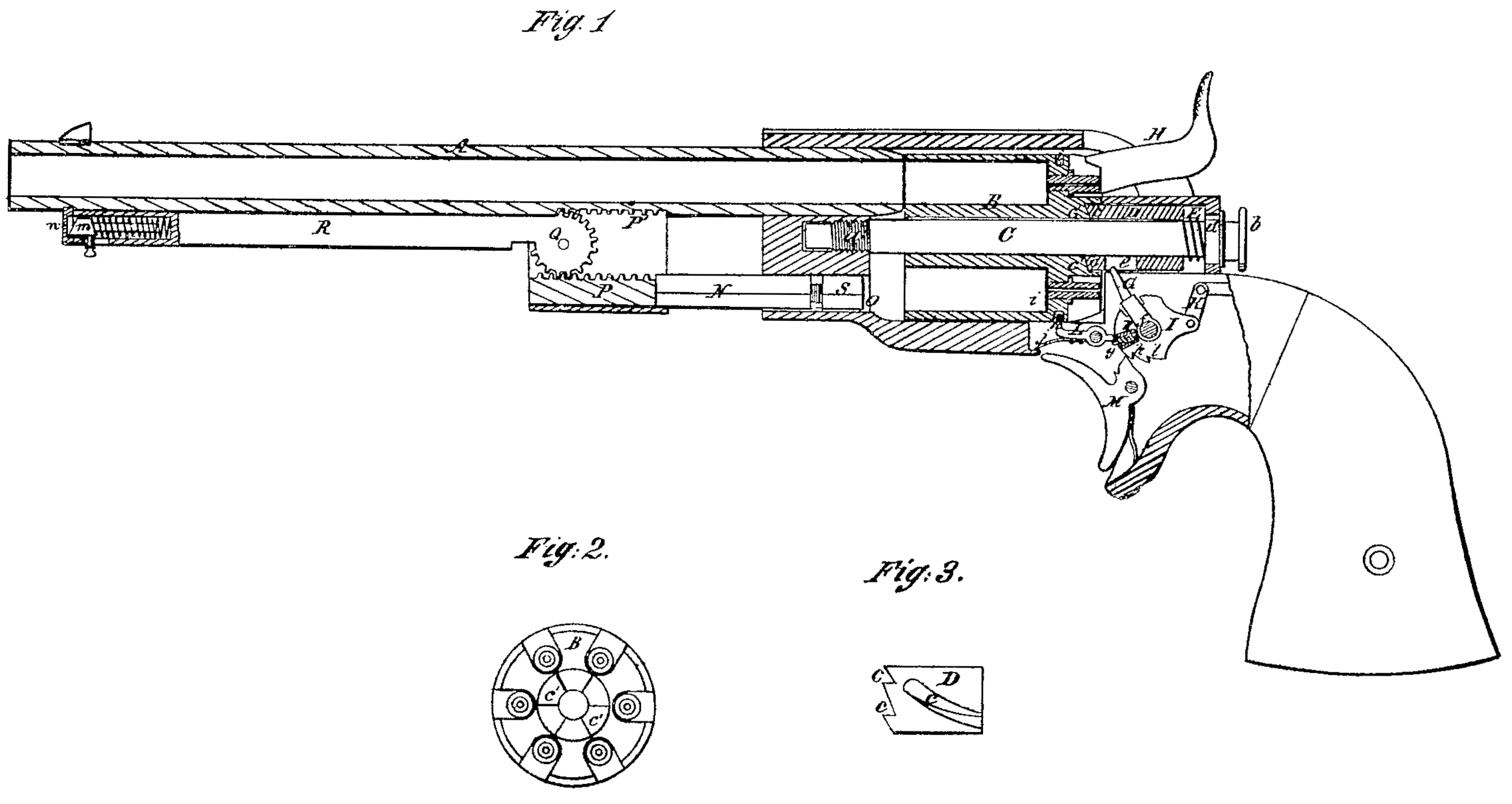
Figure 1 is a longitudinal central section of the improved pistol. Fig. 2 is an end view of the rear end of the revolving chambered cylinder. Fig. 3 is a side elevation of the slotted clutch-cylinder for moving the revolving chambered cylinder.
Similar letters in the figures refer to corresponding parts.
The nature of this invention consists in combining and arranging a series of parts in such relation to the hammer-shaft as to enable it to operate upon the same in such a manner as to operate upon the same in such a manner as by the act of cocking the hammer.
To enable others skilled in the art to make and use my invention, I will proceed to describe its construction and operation.
The barrel A and revolving cylinder B are situated in the same relation to each other as in Colt’s revolver. The cylinder is revolved on a shaft or arbor, C, inserted through the center of the same and secured by a screw, which readily admits of their being detached when occasion may require. This shaft or arbor is provided with a screw, a, at its forward end, which enters a corresponding female screw in the body of the pistol and extends some distance in the rear of the cylinder, its rear end being provided with a serrated shoulder, b, upon which the thumb and forefinger can be operated after the manner of an ordinary thumbscrew. Surrounding the rear part of this shaft is a revolving clutch-cylinder, D, which is made to exactly fit the same, on the forward end of which are formed notches c, which enter and exactly fit in corresponding notches, c’, made in the rear end of the cylinder. This revolving clutch is pressed against the end of the said body of metal by means of a spiral spring, E, which surrounds the arbor C, and is compressed between the ends of the revolving clutch and a shoulder, d, made near the end of the arbor, in such a manner as to enable the clutch to be pressed with the required degree of force against the corresponding notched end of the cylinder to engage with them. A spiral slot, e, is formed in this clutch, extending from its rear end at such an angle and to the proper distance to enable a radial or curved arm, G, secured on the shaft f of the hammer H or the tumbler I, to enter the same and to turn the cylinder in its passage through said slot the required distance to bring the next succeeding chamber opposite the barrel of the pistol. In turning back, however, the spring E yields enough to allow the clutch-cylinder D to revolve without turning the cylinder B, the notches c being so inclined that they act on the notches c’ in one direction while they slide over them in the other one.
The tumbler I is connected to the ordinary lock, arranged and secured in the stock by means of a connecting-link, K, and has a radial opening formed in it below the radial or curved arm G, in which is inserted a small dog, g, whose angular or curved end projects a short distance beyond the periphery of the tumbler by means of a spiral spring, h’, placed in the radial opening, so as to cause its elasticity to be exerted on the inner end of the dog g, and to keep the outer end of the same the required distance beyond the periphery of the tumbler to cause it to operate on the end of a lever or bar, L, when the hammer is drawn back. The front end of the lever L is turned up and forms a stop, h, fitting into corresponding notches, i, in the surface of the cylinder B, and it is held in this position by a spring, j, which forces the front end of the lever L up until the dog g comes in contact with its rear end and releases the stop h. The dog g operates on the end of the lever L as soon as the tumbler is moved, and the stop his drawn back from the notch i before the lever G begins to revolve the cylinder by operating on the slot e, and as soon as the stop his lifted high enough the cylinder begins to revolve, and by the time the dog g has passed up far enough to let the lever L fall back the cylinder B has revolved by the action of the lever G far enough to prevent the stop h from entering one of the notches i. By this time the end of the trigger M enters the first notch, k, in the tumbler I and the pistol is at half-cock. When the hammer is drawn farther back the cylinder B revolves, and as soon as the next chamber is opposite to the barrel another of the notches, i, is brought opposite the stop h and the cylinder is arrested in the required position. At the same time the end of the trigger M enters the second notch, l, in the tumbler and the pistol is cocked. In coming back the inclined side of the dog g strikes against the end of the lever L and the dog g is forced in, compressing the spring h’, which brings the dog out again to its former position after having passed the lever L.
The ramrod N works into a socket, O, in the stock corresponding to the position of one of the chambers, and its front end has a toothed rack, P, on its upper side, and similar teeth are provided on the under side of the barrel, at P’, in such a position that a toothed segment, Q, gears into both the racks P and P. A lever, R, is attached to the segment Q, and by turning this lever the segment Q causes the rod N to descend, so that the charge can be rammed down with great rapidity and power. The lower end of the ramrod has a separate piece, S, attached to it by means of a screw, so that the length of the ramrod may be adapted to different charges. The upper end of the lever R is provided with a sliding catch, m, fitting in to a corresponding socket, n, at the under side of the barrel, so that the lever R, when turned up, is firmly secured close under the barrel.
Having thus described my invention, what I claim as new, and desire to secure by Letters Patent, is—
Revolving the cylinder B by means of a slotted spring-clutch cylinder, D, operated by a lever, G, as described.
B. F. JOSLYN.
Witnesses:
J. F. Buckley,
Mich. Hughes.