
US 20144
UNITED STATES PATENT OFFICE.
SAMIL. COLT, OF HARTFORD, CONNECTICUT,
IMPROVEMENT IN REVOVING FIRE-ARMS.
Specification forming part of Letters Patent No. 20,144, dated May 4, 1858,
To all whom it may concern:
Be it known that I, Samuel Colt, of Hartford, in the State of Connecticut, have made certain new and useful Improvements in Many-Chambered Rotating-Breech Fire-Arms; and I do hereby declare that the following is a full, clear, and exact description thereof, reference being had to the accompanying drawings, making part of this specification, in which—
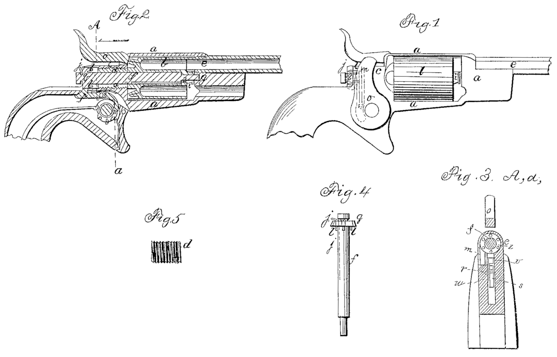
Figure 1 is a side elevation ; Fig. 2, a longitudinal vertical section; Fig. 3, a cross vertical taken at the line A a of Fig. 2; Fig. 4, a separate view of the central pin, and Fig. 5 a separate view of the adjusting-screw through which the central pin passes.
The same letters indicate like parts in all the figures.
The nature of my said invention consists in making the central pin on which the many-chambered breech rotates so that it can be inserted and taken out from behind, and when inserted pass entirely through the central bore of the rotating breech, to which it is feathered or otherwise connected, so that the breech shall be rotated by the turning of the pin, which is, nevertheless, free to be inserted or withdrawn When the head of the said central pin is formed with ratchet-teeth or equivalents for operating the rotating breech, and the forward end of it is made to enter the framing in front for support.
In the accompanying drawings, a represents the metal frame surrounding the rotating breech b, with a hole through the back part or shield-plate, c, tapped to receive an adjusting screw, d, the forward end of which bears against the rear end of the breech to adjust its forward end to the rear end of the barrel e, which projects some distance within the frame a. The rear end of this screw does not extend through to the back of the shield-plate, there being sufficient space left behind it for the working of the mechanism by which the breech is rotated. This adjusting-screw is hollow to receive the central pin, f, which also passes through the central bore of the breech, its forward end entering a recess in the front part of the frame a at g to give the required support. The central bore of the breech is cylindrical from the rear end to within a short distance of the forward end, where it is made of reduced diameter, as at h, and the central pin is made of corresponding form to fit it accurately and yet so freely that it can be put in and taken out readily. The pin is grooved to fit a feather or pin in the bore of the breech, by which the two are clutched that the one shall turn with the other. Any equivalent for this may be substituted.
The breech is formed with a tubular projection or sleeve, i, at the forward end, surrounding the small part of the central pin and extending forward nearly to the front part of the frame, and the forward part of this sleeve is swelled, as represented in the drawings. The smoke and gases escaping from the junction of the breech and barrel will strike the said sleeve and will be thereby prevented from entering between the central pin and bore of the breech, the swell of said sleeve at its forward end still further increasing the protection against the fouling effects of the smoke and gases. The rear end of the central pin is provided with a spring-catch, j, which enters a groove in the bore of the adjusting-screw, by which the pin is held in its place; and this spring extends out at the rear, as at j, so that it can be readily depressed with the thumb-nail when the pin is to be taken out to remove the breech.
Ratchet-pins l, equal in number to the number and position of the chambers in the breech, project from the inner face of the head g of the central pin f, and these pins are acted upon to rotate the central pin, and with it the chambered breech, to bring the chambers in succession to the line of the barrel, by a spring dog or pawl, m, which is connected at its lower end by a joint-pin with the inner face of the hammer, so that as the hammer is elevated from the nipples, or cocked, the dog or pawl will be depressed to turn the breech and bring a loaded chamber in line with the barrel, and as the discharge takes place the dog is elevated to be in the proper position for again turning the breech at the next operation. It is necessary, however, that the rotating breech should be locked, to prevent it from being accidentally turned, from the time the hammer is cocked until the load is discharged. This is effected by one end of a lever, p, entering notches in the periphery of the head q of the central pin, f. This lever turns on a fulcrum-pin, t, and one end of it is curved and lies by the side of the tumblers, and it is made sufficiently thin to spring laterally. Its lower end projects inward toward the axis of the tumbler and cock, as at v, to be acted upon by a cam-like tappet, w, on the tumbler. The upper face of the tappet and the under face of the projection on the lever are parallel— that is, at right angles to the plane of motion of the tumbler— and the tappet is so located that at the moment of beginning to elevate the hammer it shall act on the lever and draw the end p out of one of the notches in the head of the central pin, f, and thus unlock it, so that it may be turned and with it the rotating breech, and then pass above the projection on the lever, that the locking end of the lever may be carried back by its spring to relock the central pin and breech preparatory to the discharge; and to permit the lever to remain in its locked position during the discharge, the upper face of the projection on the lever and the underface of the tappet are beveled, so that the tappet in descending may spring the lever laterally and pass by the projection without turning the lever on its fulcrum.
It will be obvious from the foregoing that the construction of the parts and their arrangement may be greatly modified and equivalent devices substituted without changing the mode of operation of my invention; and therefore I wish it to be distinctly understood that I do not limit myself to the special construction or arrangement, so long as the same mode of operation is retained.
I claim as new—
In combination with a central pin which is inserted from behind to admit of readily taking out and replacing the rotating breech, and which is feathered or otherwise fitted to the central bore of the rotating breech so as to turn therewith, and which passes entirely through the central bore of the said rotating breech and into the framing in front for support, the making of the rear end or head of the said central pin with ratchet-teeth, or the equivalent thereof, to be acted upon by the mechanism for turning and holding the rotating breech, all substantially as and for the purpose described.
SAM. COLT.
Witnesses:
J. W. STANCLIFF,
E. K. ROOT.