
US 183944
UNITED STATES PATENT OFFICE.
BENJAMIN F. JOSLYN, OF WORCESTER, MASSACHUSETTS.
IMPROVEMENT IN REVOLVING FIRE-ARMS.
Specification forming part of Letters Patent No. 183,944, dated October 31, 1876; application filed March 9, 1876.
To all whom it may concern:
Be it known that I, BENJAMIN F. JOSLYN, of Worcester, Massachusetts, have invented Improvements in Revolving Fire-Arms, of which the following is a specification:
The object of my invention is to so make the frame of a revolver in two parts, hinged together, that one part may be turned to one side, and expose the whole of the bores of the cylinder for the introduction and simultaneous extraction of the whole of the cartridges. This object I attain in the manner which I will now proceed to describe, reference being had to the accompanying drawing, in which–
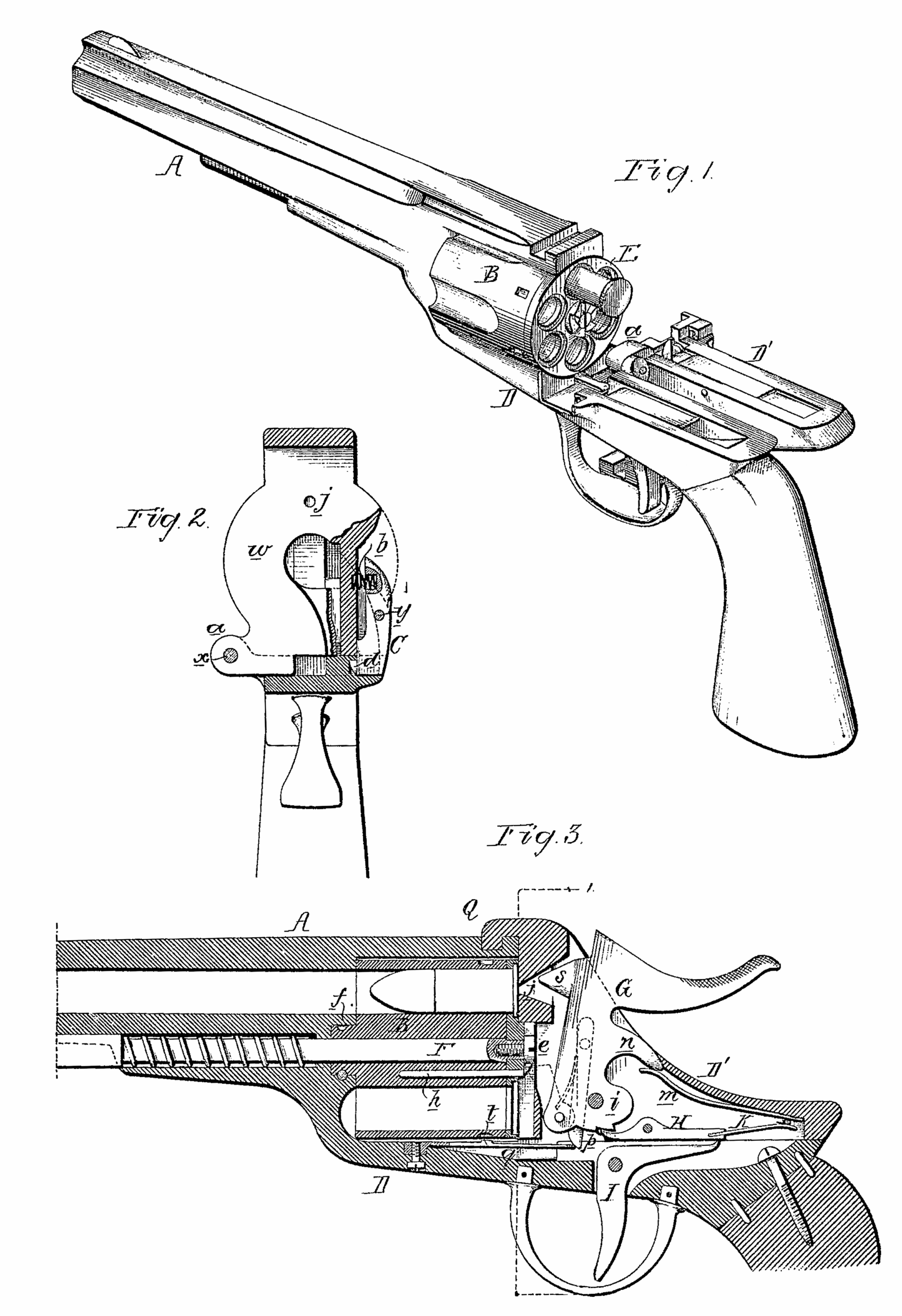
Figure 1 is a perspective view of a revolver with my improvements; Fig. 2, a transverse section on the line 1 2, looking in the direction of the arrow; and Fig. 3, a longitudinal section.
A is the barrel of the revolver; B, the cylinder; D, the fixed frame carrying the barrel; and D’, the movable frame, which has a lug, a, hinged by a pin, x, to lugs on the said fixed frame, so that it can be tilted laterally to the position shown in Fig. 1, thereby exposing the entire rear of the cylinder B.
A lever, C, is hung by a pin, y, to the movable frame D’, the upper arm of the said lever being so acted on by a spring, b, as to maintain a projection, d, on the lower arm in a recess in the fixed frame, to which the movable frame is thus locked until the upper arm is pressed so far inward as to withdraw the said projection, which is beveled on one side, so that the movable frame will be self-locking to the fixed frame.
In front of the cylinder B is a circular projection, f, adapted to a bearing in the fixed frame, the projection being secured by a pin which permits the cylinder to turn freely, but prevents it from being moved rearward. A pin, F, passes through the fixed frame beneath the barrel, and to this pin is secured, by a screw, e, the extracting-plate E, which has openings corresponding with the bores of the cylinder, each opening being countersunk for the reception of the flanged head of a metallic cartridge.
A spring coiled around the pin F tends to maintain the extracting-plate in close contact with the rear end of the cylinder, and a pin, h, prevents the plate from turning independently of the said cylinder. The hammer G is hung by a pin, i, to the movable frame D’, and has the usual spring-pawl adapted to a ratchet on the extracting-plate. The movable frame also carries a lever, H., one arm of which is acted on by a spring, K, the other arm being adapted to notches in the lower portion of the hammer G.
The trigger, which is pivoted to the fixed frame, consists of a bell-crank lever, the pendent arm of which is in a proper position to be manipulated by the finger, the other arm being in contact with the long arm of the spring-lever H, when the movable frame is locked in its place. The mainspring m, which is also contained within the movable frame, bears against the underside of the projection in of the hammer.
An arm, p, projects from the hammer, and, when the movable frame is locked, this arm bears with its lower rounded end against a spring, q, which is secured to the fixed frame, and which has a projection, t, adapted to notches in the barrel. The end of the arm p and spring q are so situated in respect to each other, and to the pivot-pin of the hammer, that, on cocking the hammer, the spring will be depressed and the cylinder will be unlocked, so that it can be turned by the action of the usual pawl and ratchet. The hammer cannot fall, however, and strike the cartridge before the spring is released, and the cylinder is thereby locked.
The front of the movable frame forms the breech w, which is cut away, as shown in Fig. 2, for the admission of the ratchet which projects from the extracting-plate, the breech. having an opening, j, for the reception of the striking-heads of the hammer.
When the movable frame is locked in its place, a lip, Q, on the said frame fits snugly in a recess in the barrel, and is thus effectually locked thereto. When the movable frame is turned back, as shown in Fig. 1, all the bores of the barrel, and the corresponding countersunk openings of the extracting-plate, are exposed, so that all the spent cartridges may be simultaneously expelled by moving the rod F rearward.
I am aware that a revolver has heretofore been constructed so as to expose the breech plate of the cylinder by turning the whole stock and frame to one side; but this is found to be objectionable on account of its clumsiness and the inconvenience in handling.
I claim as my invention–
The combination, in a revolver, of a cylinder and a fixed frame and stock, D, with the movable breech portion D’, hinged to one side of the fixed stock, substantially as set forth.
In testimony whereof I have signed my name to this specification in the presence of two subscribing witnesses.
BENJAMIN E. JOSLYN.
Witnesses:
HARRY SMITH,
HARRY HOWSON, JR.