
US 261554
UNITED STATES PATENT OFFICE.
MICHAEL KAUFMANN, OF LONDON, ENGLAND.
REVOLVING FIRE-ARM.
SPECIFICATION forming part of Letters Patent No. 261,554, dated July 25, 1882.
Application filed April 20, 1882. (No model.) Patented in Belgium October 15, 1878, and August 20, 1881, No. 55,511; in France April 20, 1881, No. 142,426; in England September 9, 1881, No. 3,913, and in Italy February 11, 1882, No. 13,834.
To all whom it may concern:
Be it known that I, MICHAEL KAUFMANN, a subject of the Queen of Great Britain, residing at London, in the Kingdom of England, have invented certain new and useful Improvements in Revolving or Repeating Fire-Arms; and I do hereby declare the following to be a full, clear, and exact description of the invention, reference being bad to the accompanying drawings, and to the figures and letters of reference marked thereon, which form a part of this specification.
My invention relates specially to solid-frame or rod-extracting revolving fire-arms in which the lock is provided with a rebounding hammer, but is also applicable to other kinds of revolving or repeating fire-arms which have a door, gate, movable shield, or hinged covering-plate at the rear of the cylinder, or which are loaded in the same manner as a solid-frame or rod-extracting breech-loading revolving fire-arm.
The object of my invention is to provide the lock of any such fire-arms with a stop or locking device which locks the cylinder or keeps it securely fixed after each rotation and when not in use, the essential feature of my invention being that I utilize the gate or hinged covering-plate for the purpose of freeing the cylinder from said stop or locking device, so that the cylinder may rotate freely, when desired, in order that the fire-arm may be loaded, and, if a rod-extracting revolving fire-arm, to permit also the extracting of the cartridges. I attain my object by so arranging the door, gate, movable shield, or hinged covering-plate that when operated by being opened to give access to the rear of the cylinder for the purposes of extracting the cartridges or loading the fire-arm a prolongation, extension, or tail piece of the door, gate, shield, or hinged cowering-plate will act on the hammer, and through its medium on the trigger, thereby releasing the cylinder from the said stop or locking device.
I shall now proceed to describe my invention as applied to a revolver somewhat similar in construction to that described in the specification to Letters Patent of the United States No. 212,473, dated 18th February, 1879, reference being had to the accompanying drawings, in which–
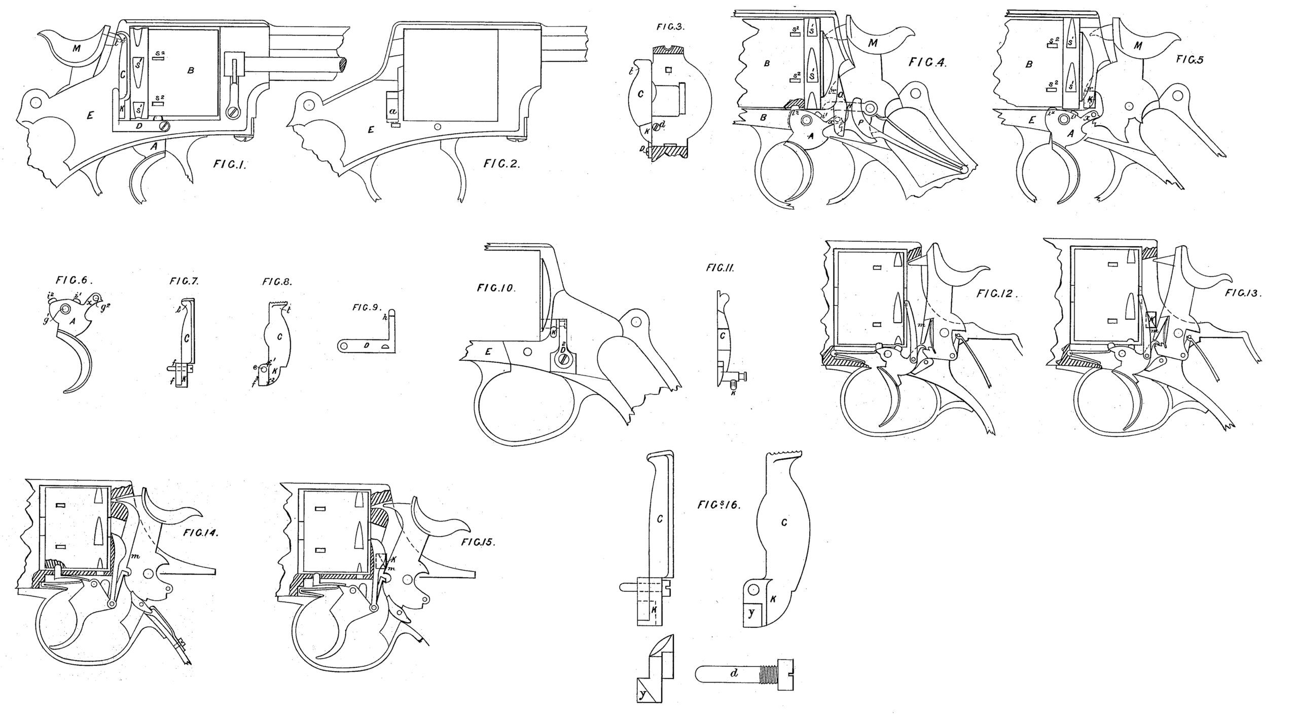
Figure 1 represents a side elevation of the revolver, which shows the door, gate, or hinged covering-plate at the rear of the cylinder, with a spring on the exterior of the revolver acting on the said door or gate. Fig. 2 is a view of the exterior of the revolver, the lock, cylinder, gate, and spring having been removed, showing an opening in the frame or body of the revolver, through which the prolongation or extension of the gate acts. Fig. 3 is a sectional view, showing part of the frame or body at the rear of the cylinder, the gate, door or hinged covering-plate being attached. Fig. 4 is a side elevation of the revolver with the lock exposed, showing all the parts in their respective places, the hammer resting in its normal position. Fig. 5 is a similar view of the same revolver, showing the prolongation of the gate acting on the hammer, and through its medium on the trigger, the other parts of the lock having been removed. Fig. 6 is a side elevation of the trigger. Figs. 7 and 8 are views of the door, gate, movable shield, or hinged covering-plate. Fig. 9 is a plan showing the inner face of the gate-spring. Figs. 10 and 11 are side and rear elevations of a modified form of device. Figs. 12, 13, 14, and 15 show my invention applied to various forms of locks. Fig. 16 is a side and rear elevation, on an enlarged scale, of the gate.
A indicates the trigger; B, the cylinder; C, the door, gate, movable shield, or hinged covering-plate; K, the prolongation, extension, or tail-piece of the gate or hinged covering plate; D, the gate-spring; E, the main frame or body; H, the central lever; M, the hammer; O, the pawl; P, the lock-spring.
The main frame E is provided with an opening, a, (shown in Fig. 2,) to receive the prolongation or tail-piece K of the gate C. A hole is formed in the main frame E to receive a screw, d, (see Figs. 3 and 16,) the said screw being made partly with a smooth surface to serve as a pivot or axle for the gate C. The gate C is perforated at e (shown in Fig. 8) for its pivot or axle d. (See Figs. 7 and 16.) The pivot or axle d enters the main frame at the rear of the cylinder, passes through the hole e of the gate C, again enters the main frame behind the gate C, and is finally screwed into the mainframe, as shown in Fig. 3.
The gate C is constructed with a prolongation or tail-piece, K, and is provided with a shoulder or lug upon whose two sides, f’ and f2, which form an angle, the gate-spring D acts. The gate-spring D is of the shape illustrated, and is fastened by means of a screw to the exterior of the revolver, as shown in Fig. 1, and the end h of the gate-spring D (shown in Fig. 9) acts on the side f2 of the shoulder or lug on the prolongation K, in order to keep the gate C in its normal position, covering the rear of the cylinder, and acts also on the side f’ of the shoulder or lug on the prolongation K when the gate C is operated, in order to gain access to the rear of the cylinder.
The cylinder B is of the usual form, and is provided with two series of notches or grooves (the one series indicated by S’ and the other by S2 in Figs. 1, 4, and 5,) adapted to engage respectively with the lugs or stops i’ and i2 of the trigger A.
The trigger A is of the shape shown in Fig. 6, perforated at g’ for its pivot or axle and at g2 to receive the pivot of the pawl O, and is provided on its upper surface with a lug or stop, i’, which enters one of a series of notches, S’, on the cylinder when the weapon is full cocked, and is likewise provided on its upper surface, at its front head, with a lug or stop, i2, which, when the trigger returns to its normal position after the weapon has been fired, enters one of a series of notches, S2, on the cylinder.
The pawl O is identical in shape and function with the pawl described in the Letters Patent previously referred to.
The hammer M is of the shape illustrated, having on its forward side the projection w, but in other respects is likewise identical in shape and function with the hammer described in the before-mentioned Letters Patent.
The lock-spring P and the central lever, H, are of the shape illustrated, and are so disposed as to perform respectively the functions of the “mainspring” and the “arm” described in the before-referred-to Letters Patent, No. 212,473.
The operation is as follows: On operating the hammer or trigger for the purpose of cocking or firing the weapon the trigger turns on its pivot, and by this movement the lug or stop i2 of the trigger A is withdrawn from one of the notches or grooves S2 of the cylinder, permitting the pawl O to rotate the cylinder until a fresh cartridge is brought in a line with the barrel, when, the hammer being at full-cock, the lug or stop i’ enters one of the notches or grooves S’ on the cylinder. The trigger being retracted or drawn back, the hammer falls. Upon releasing the trigger the pressure of the lock-spring P, delivered through the medium of the central lever, H, and the pawl O, carries the projection x of the trigger downward, causing the trigger to turn on its pivot until it resumes its normal position, and by this movement the lug or stop i’ of the trigger A is disengaged from the cylinder, and the lug or stop i2 of the trigger A enters one of the series of notches or grooves S2 on the cylinder and securely holds or locks the cylinder. To permit the empty cartridges to be extracted or to load the cylinder it is necessary to liberate the cylinder, to effect which one has only to perform the usual act of opening the gate or hinged covering-plate at the rear of the cylinder. Thus, on pushing outward the summit t of the gate C it turns on its pivot, and by this action the prolongation or tail piece K of the gate C ascends, and the side f3 of the prolongation K of the gate, coming under the projection w of the hammer M, lifts the hammer, and through the medium of the hammer raises the projection x of the trigger A, thereby turning the trigger A on its pivot until the lug or stop i2 of the trigger A is disengaged from a notch S2 on the cylinder, thereby permitting the cylinder to turn freely, in order that the cartridges may be extracted or the cylinder loaded. In this position the prolongation K of the gate C, being above and near to the projection x of the trigger A, impedes any movement of the trigger, and consequently the hammer is unable to act, and there can be, therefore, no danger of a discharge of a cartridge while the gate or hinged covering-plate remains open. On pushing outward the summit t of the gate C the gate-spring D engages with the side f’ of the shoulder or lug on the prolongation K of the gate, and when the gate C is opened to its full extent it is held securely in this position by the gate-spring D. On pushing back the gate C to its normal position at the rear of the cylinder the gate spring D engages with the side f2 of the shoulder or lug on the prolongation K of the gate O and holds the gate in position. By the action of the gate C in returning to its normal position the side f3 of the shoulder or lug on the prolongation K disengages from the projection w of the hammer, and the prolongation K resumes its place in the opening a of the main frame E flush with the interior of the main frame. The hammer M being disengaged from the prolongation K of the gate, the lock-spring P, acting on the central lever, H, causes all the parts of the lock to return to their normal position.
I may modify the arrangement I have immediately above described, as shown in Figs. 10 and 11, in which it will be seen that the gate C, with its axle or pivot, is of one piece. In this case the opening a in the main frame E is dispensed with, the axle or pivot of the said modified gate C entering a hole made to receive it in the main frame in rear of the cylinder at about the same point as the screw d in Fig. 3. The axle is provided with two sides, forming an angle adapted to engage with a spring fixed in the interior of the main frame E, which spring holds the gale securely in its normal position and when operated in the manner as hereinbefore described. In this modification the tail-piece of the gate C is detached, and is screwed or fixed into the axle of the gate C after the axle has entered the main frame and the gate is in position.
In applying my mode of freeing the cylinder by the action of the gate to ordinary locks such, for example, as shown in Figs. 12 to 15, inclusive, in which the hammers have not the projection w of the arrangement first described–I modify the gate C by forming on the prolongation K thereof an inclined plane, as shown at y, Fig. 16, tapering to the front or end nearest in proximity to the hammer, the base of this wedge-like prolongation being farthest from the hammer when the prolongation K rests in its normal position in the main frame E, whereby the prolongation, when operating, has an effect similar to that of a wedge. Thus, when the gate C is operated in the manner as hereinbefore described the inclined plane y of the prolongation K, at its thin or narrow end, engages with the forward side, m, of the hammer, and as the prolongation K advances it lifts or forces up the hammer, and through the medium of the hammer liberates the cylinder, as shown in Figs.13 and 15. The modified gate C, with inclined plane, is shown detached and drawn to an enlarged scale at Fig. 16.
Figs. 12 and 14 show the above-referred-to locks as they appear when not being operated by the gate C.
I may also modify the arrangement of freeing the cylinder in other ways than those above described–as, for instance, the cylinder may be locked with an arm attached to the trigger, as shown in Fig. 14, and this arm may be projected also in an opposite direction, and the prolongation of the gate may be arranged to operate direct on the rear end of the said locking-arm; or, if an arm on the trigger be made to operate a locking device on the rear part of the cylinder, the gate or hinged covering-plate may be so arranged as to act direct on the said arm or on the said locking device for the purposes of liberating the cylinder. I may also modify the gate or hinged covering plate so that it may operate direct on the trigger for the purpose of liberating the cylinder.
Having now described the nature of my said invention and in what manner the same is or may be performed, I would have it distinctly understood that I do not limit myself to the precise details hereinbefore set forth and shown in the drawings, as such may be greatly modified while retaining the essential feature of my invention–namely, the utilization of the gate or hinged covering-plate for the purposes specified; and
What I claim as new, and desire to secure by Letters Patent, is–
The combination, in a revolving fire-arm, of a step for normally locking the cylinder with one of its chambers in alignment with the barrel, with a pivoted gate and mechanism, substantially as described, intermediate the gate and stop, whereby when the gate is moved to gain access to the cylinder for loading the stop is released from engagement with the cylinder, as set forth.
In testimony whereof I affix my signature in the presence of two witnesses.
MICHAEL KAUEMANN.
Witnesses:
WILLIAM EDWARD GEDGE,
No. 11 Wellington Street, Strand, London, England.
LENNOX FORSTER SYKES,
Clerk to the above.